A Wide Viewing Angle Liquid Crystal Spatial Light Modulator

A spatial light modulator, wide viewing angle technology, applied in instruments, optics, nonlinear optics, etc., can solve the problems of insufficient dark state, slow response speed, low contrast, etc., to shorten the optical path difference, improve the viewing angle characteristics, The effect of improved viewing angle uniformity

Inactive Publication Date: 2020-06-26
UNIV OF ELECTRONICS SCI & TECH OF CHINA
View PDF3 Cites 0 Cited by
  • Summary
  • Abstract
  • Description
  • Claims
  • Application Information

AI Technical Summary

Problems solved by technology

[0006] (1). The viewing angle is narrow; when the linearly polarized light of the same intensity is incident at different angles, due to the change of the effective refractive index, it becomes elliptically polarized light. After passing through the second polarizer, the outgoing light intensity with different incident angles is no longer equal. Cause viewing angle problem, its viewing angle is less than 40°
[0007] (2). The response speed is slow; the twisted nematic mode liquid crystal light valve works in a natural fallback mode. Since there is no other external force, its response speed exceeds 40ms
[0008] (3). Low contrast; the twisted nematic liquid crystal light valve uses the optical rotation characteristics of liquid crystal, and the contrast is low, especially the dark state is not dark enough.

Method used


Image

  • A Wide Viewing Angle Liquid Crystal Spatial Light Modulator
  • A Wide Viewing Angle Liquid Crystal Spatial Light Modulator
  • A Wide Viewing Angle Liquid Crystal Spatial Light Modulator

Examples


Embodiment

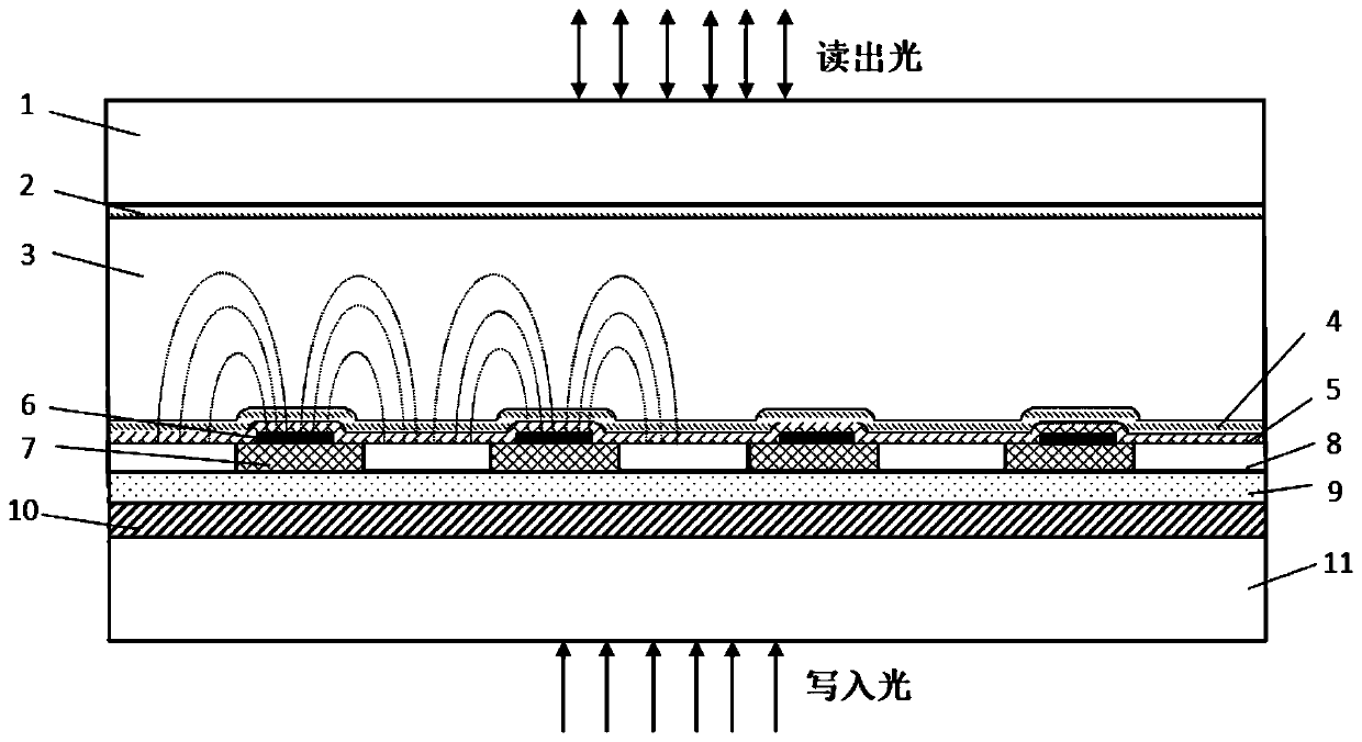
[0030] This embodiment provides a method for preparing a liquid crystal spatial light modulator, including the following steps:

[0031] Step A: preparing a photosensitive layer 9;

[0032] This embodiment directly adopts the cleaned common glass substrate as the upper glass substrate 1 and the lower glass substrate 11, and then deposits the ITO conductive layer 10 on one side of the lower glass substrate 11; The surface of 10 is deposited with a 3-8 micron thick micro-doped amorphous silicon film as the photosensitive layer 9. In this embodiment, the material of the photosensitive layer 9 is not limited to a hydrogenated amorphous silicon film. According to common knowledge in the art, the photosensitive layer 9 The material can be any suitable material;

[0033] Step B: preparing a reflective layer;

[0034] At first on the photosensitive layer 9 that step A makes adopts the electron beam evaporation method to deposit one deck thickness to be the metal Ag film 8 of 1~2 mic...


PUM

PropertyMeasurementUnit
electrical resistivityaaaaaaaaaa
viewing angleaaaaaaaaaa

Abstract

The invention provides a liquid crystal spatial light modulator with a wide viewing angle and belongs to the technical field of liquid crystal devices. The present invention adopts the pixel unit arranged in an array to form the pixel unit distributed in the photosensitive layer surface and the photosensitive area connecting each pixel unit, and fills the light-absorbing material to form a light blocking area in each pixel unit to form a reflective layer. Part of the upper surface of each light-blocking area is provided with a metal reflection unit to form a metal isolation grid. In the present invention, a conductive layer is only arranged on the surface of the glass substrate near the photosensitive area, and the photosensitive area and the conductive layer are used as an electrode together, while the metal isolation grid The grid is used as another electrode to realize the formation of a coplanar horizontal electric field between any two adjacent metal photosensitive regions and the metal reflective unit in the electrified state to drive the liquid crystal molecules. The viewing angle performance of the device can be improved based on the device structure of the present invention, so that the viewing angle can be widened, and at the same time, the photosensitivity and imaging effect of the device can be improved through the improvement of the structure.

Description

technical field [0001] The invention belongs to the technical field of liquid crystal devices, and in particular relates to a liquid crystal spatial light modulator with a wide viewing angle. Background technique [0002] A spatial light modulator (Spatial Light Modulator, SLM) means that under active control, it can modulate a certain parameter of the light field through liquid crystal molecules, such as modulating the phase through the refractive index, modulating the polarization state through the rotation of the polarization plane, or realizing The conversion of incoherent to coherent light, so as to write certain information into the light wave, achieve the purpose of light wave modulation. [0003] Spatial light modulators can generally be divided into reflective and transmissive according to the way the readout light is read out; and can be divided into optical addressing (OA-SLM) and electrical addressing (EA-SLM) according to the way of input control signals. -SLM)...

Claims


Application Information

Patent Timeline
Patent Type & Authority Patents(China)
IPC IPC(8): G02F1/1335G02F1/1343G02F1/1362
CPCG02F1/133553G02F1/134309G02F1/134363G02F1/136209
Inventor 王继岷蒋向东曾一雄高升旭董湘
Owner UNIV OF ELECTRONICS SCI & TECH OF CHINA
Why Eureka
Try Eureka