Two-stage gasification method and gasification device for fuels with wide size distribution

A technology of a gasification device and a feeding device, which is applied to the gasification of granular/powdered fuel, the production of combustible gas, and the mitigation of combined combustion, etc. The effect of flexible raw material throughput, flexible fuel throughput, and reduced processing load

Active Publication Date: 2012-10-03
INST OF PROCESS ENG CHINESE ACAD OF SCI
View PDF14 Cites 31 Cited by
  • Summary
  • Abstract
  • Description
  • Claims
  • Application Information

AI Technical Summary

Problems solved by technology

Due to the limitation of the external heating spiral pyrolyzer, the technology developed by DTU in Denmark is difficult to further scale up
In addition, this process is only suitable for processing raw materials with large particle size (25mm×35mm×6mm), and the requirements for raw material size are relatively high
Although the two-stage gasification technology developed by the University of Seoul in South Korea can process a large amount of raw materials, it greatly increases the cost of raw materials because it does not make full use of the semi-coke produced by the gasifier itself (using a large amount of commercial activated carbon).
The two-stage gasification technology announced in Chinese patent 94190559.4 is due to the direct discharge of pyrolysis gas generated by the fluidized bed, resulting in excessive tar content in the mixed gas. In practical applications, post-installed gas purification facilities are still required, which undoubtedly increases equipment cost
In the two-stage biomass gasification process disclosed in Chinese patent CN1583956A, due to the lack of catalytic actio

Method used


Image

  • Two-stage gasification method and gasification device for fuels with wide size distribution
  • Two-stage gasification method and gasification device for fuels with wide size distribution
  • Two-stage gasification method and gasification device for fuels with wide size distribution

Examples


Example Embodiment

[0041] The present invention will be described below with reference to specific embodiments. These embodiments are only used to illustrate the purpose of the present invention and do not limit the scope of the present invention in any way.

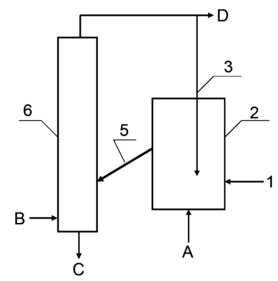
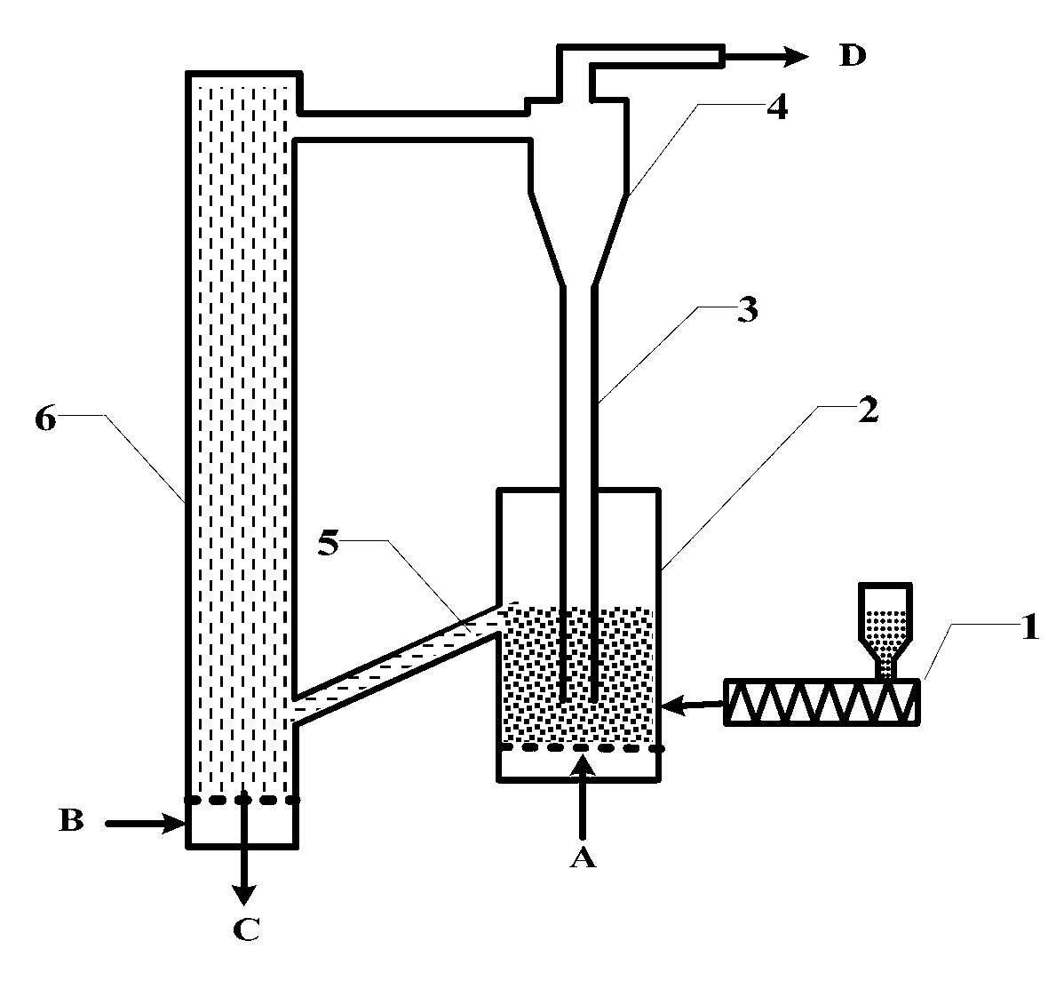
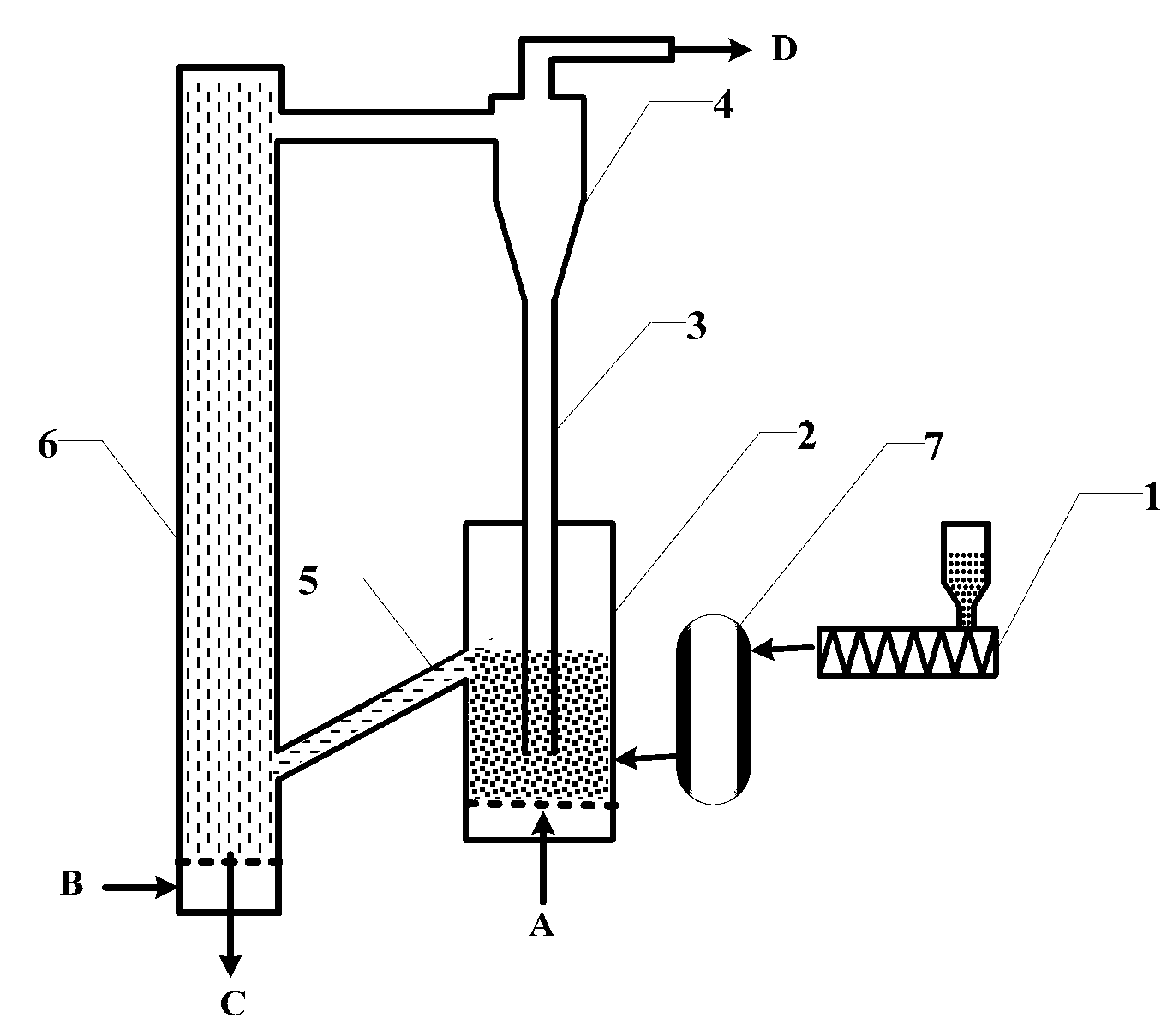
[0042] The two-stage gasification method for solid fuel with wide particle size distribution of the present invention includes the following steps:

[0043] 1) The fuel is fed into the fluidized bed pyrolyzer through the feeding device, and gasification agent is added to the fluidized bed pyrolyzer at the same time, and the fuel is dried / heated under the heating of the semi-coke and gasification agent of the pyrolyzer Decomposition or partial gasification to produce solid products containing semi-coke and gas products containing pyrolysis gas, tar or steam;

[0044] 2) The solid and gas products produced in step 1) are fed into the entrained bed gasifier together, and gasification agent is added to the entrained bed gasifier to complete the compl...


PUM


Abstract

The invention relates to a two-stage gasification method and a gasification device for a fuel with wide size distribution. The two-stage gasification method for the fuel with wide size distribution comprises the steps of 1) adding the fuel to a fluidized bed pyrolyzer by a feeding device; adding a gasifying agent to the fluidized bed pyrolyzer; drying/pyrolyzing or partly gasifying the fuel under semicoking of the pyrolyzer and heating of the gasifying agent; and 2) sending the solid and gas generated in the step 1) to a fluidized bed gasification furnace, adding the gasifying agent to the fluidized bed gasification furnace, finishing complete gasification of semicoke; removing tar by high-temperature pyrolysis, part oxidization and semicoke catalytic reforming in the fluidized bed so as to produce clean gas. With the adoption of the method, the traditional fuel gasification process is divided into a material pyrolysis stage and a semicoke gasification stage, which are performed in an upper fluidized bed pyrolyzer and a lower fluidized bed gasification furnace.

Description

technical field [0001] The invention relates to the technical field of clean energy, in particular, the invention relates to a two-stage gasification method for fuel with wide particle size distribution and a gasification device thereof. Background technique [0002] Gasification is one of the leading ways to convert carbon-containing fuels such as coal and biomass, and is an important technical means to realize their comprehensive and clean utilization. This technology is widely used in chemical industry, metallurgy, civil and industrial gas, building materials, ceramics and other fields. It is a leading technology for the development of these industries and an important measure to reduce environmental pollution, save energy and develop industries. At present, the fixed-bed gasifiers commonly used in the domestic gas industry are backward in technical level, and generally have problems such as poor raw material applicability, small processing capacity, difficult amplificati...

Claims


Application Information

Patent Timeline
IPC IPC(8): C10J3/56C10J3/66C10J3/84
CPCY02E20/18
Inventor 许光文汪印曾玺张聚伟赵志刚
Owner INST OF PROCESS ENG CHINESE ACAD OF SCI
Why Eureka
Try Eureka