Moving picture coding apparatus and moving picture decoding apparatus

A moving image and decoding device technology, applied in image coding, code conversion, image communication, etc., can solve problems such as inability to obtain compression characteristics, impossibility of encoding error lossless encoding processing, etc.

Inactive Publication Date: 2004-05-12
MITSUBISHI ELECTRIC CORP
View PDF0 Cites 34 Cited by
  • Summary
  • Abstract
  • Description
  • Claims
  • Application Information

AI Technical Summary

Problems solved by technology

[0009] Since the conventional moving picture coding device and moving picture decoding device are constituted as above, the moving picture coding method adopted usually adopts DCT as the conversion method for converting to the frequency region of the image signal. When the conversion characteristics of the input and DCT are different There is a problem that sufficient compression characteristics cannot be obtained when a suitable signal is used
In addition, in the conventional combination of DCT and quantization, there is a problem that it is practically impossible to achieve lossless encoding processing with zero encoding error

Method used


Image

  • Moving picture coding apparatus and moving picture decoding apparatus
  • Moving picture coding apparatus and moving picture decoding apparatus
  • Moving picture coding apparatus and moving picture decoding apparatus

Examples


Embodiment 1

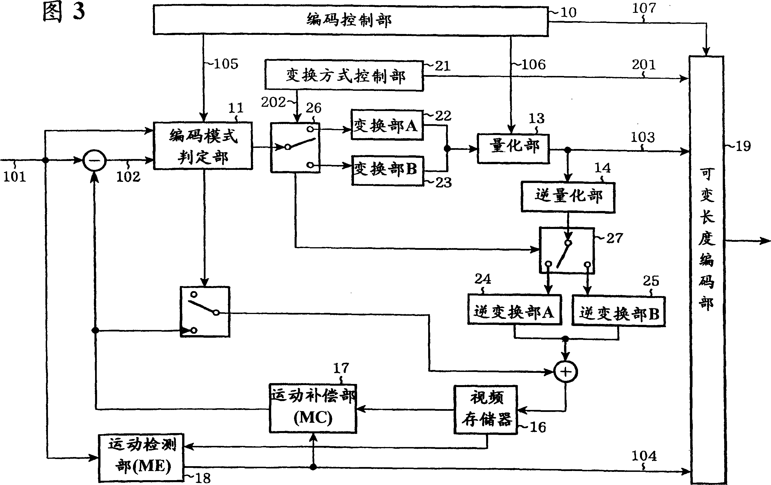
[0056] Fig. 3 is a block diagram of an image coding apparatus according to Embodiment 1 of the present invention.

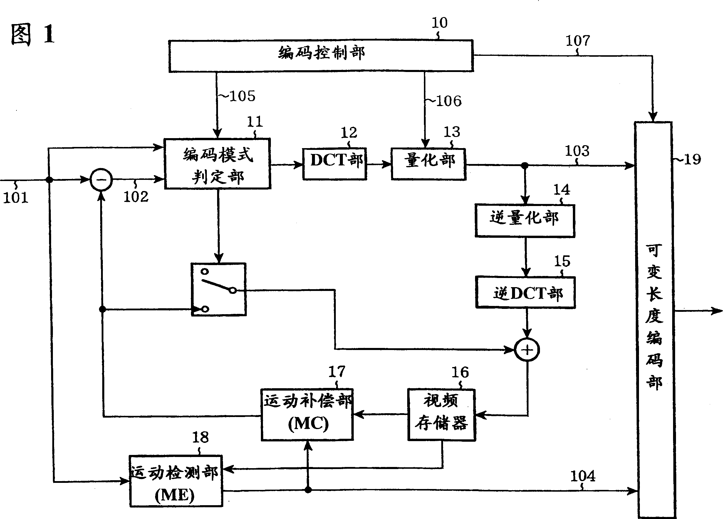
[0057] In the figure, 21 is a conversion mode control unit, 22 is a first conversion unit A, 23 is a second conversion unit B, 24 is a first inverse conversion unit A, 25 is a second inverse conversion unit B, 26, 27 are switches, It is used to select one of the two transformation units A 22 , B 23 and inverse transformation units A 24 , B 25 . Other constituent elements are the same as those of the conventional example shown in FIG. 1 , and modules with the same numbers have the same functions and perform the same operations.

[0058] Next, the operation will be described. As a process of converting the signal output by the encoding mode determination unit 11 from the spatial domain to the frequency domain, the conversion method control unit 21 uses the signal 202 to control the switch 26 to select from the two prepared conversion units A 22 and B 23. One to p...

Embodiment 2

[0067] Fig. 4 is a block diagram showing the structure of an image coding apparatus according to Embodiment 2 of the present invention. In the figure, the transform method control unit 31 is different from the first embodiment in that it operates according to a signal from the encoding control unit 30 . Therefore, it is characterized in that the operation of transmitting the conversion method selection flag 201 to the decoding device side necessary in the first embodiment becomes unnecessary, or the number of times of transmission can be reduced.

[0068] Next, the operations of the encoding control unit 30 and the conversion scheme control unit 31 in the second embodiment will be described in detail. The conversion method control unit 31 executes the switching operation of the switches 26 and 27 based on the signal 203 from the encoding control unit 30 . As a method for the conversion method control unit 31 to perform operation control based on the signal 203 from the encodi...

Embodiment 3

[0083] Fig. 5 is a block diagram showing the structure of an image coding apparatus according to Embodiment 3 of the present invention. In the figure, except that an encoding control unit 40, two different quantization units 42, 43, two different inverse quantization units 44, 45 are provided, and the switch 27 is deleted, it is the same as the first embodiment shown in FIG. 3 .

[0084] Next, the operation will be described. For example, when the switch 26 selects the first transform unit A22 based on the signal 202 from the transform method control unit 21, the signal converted by the transform method of the first transform unit A22 is quantized according to the transform method. That is, it is quantized in the quantization unit A 42 having a quantization characteristic that can improve coding efficiency, and then output to the variable-length coding unit 19 as a quantization coefficient 211 for coding. Simultaneously, this quantized coefficient 211 is inversely quantized i...


PUM


Abstract

A motion picture encoding apparatus for encoding a motion picture signal includes a plurality of transform units for different transform schemes, and a transform scheme control unit for selecting, from the plurality of the transform units, the transform unit for the transform scheme adapted to the motion picture signal.

Description

technical field [0001] The present invention relates to a moving picture encoding device which compresses a moving picture signal for transmission and a moving picture decoding device which expands the compressed moving picture signal for reproduction. Background technique [0002] Fig. 1 is a block diagram of a conventional moving picture coding apparatus as shown in, for example, the international standard ISO / IEC13818-2 (commonly called MPEG-2 video part). 10 is an encoding control unit, 11 is an encoding mode determination unit, 12 is a DCT unit, 13 is a quantization unit, 14 is an inverse quantization unit, 15 is an inverse DCT unit, 16 is a video memory, 17 is a motion compensation unit, and 18 is a motion detection unit Section 19 is a variable length coding section. [0003] Next, the operation will be described. The difference between the input video signal 101 and a motion compensation prediction signal described later is obtained, and the prediction difference s...

Claims


Application Information

Patent Timeline
Patent Type & Authority Applications(China)
IPC IPC(8): H04N19/12G06T9/00H03M7/30H03M7/40H04N19/126H04N19/13H04N19/134H04N19/136H04N19/139H04N19/14H04N19/146H04N19/159H04N19/16H04N19/166H04N19/172H04N19/174H04N19/176H04N19/177H04N19/423H04N19/46H04N19/503H04N19/51H04N19/513H04N19/577H04N19/593H04N19/60H04N19/61H04N19/625H04N19/70H04N19/85H04N19/90H04N19/91
CPCH04N19/00145H04N19/00375H04N19/00109H04N19/00024H04N7/26106H04N19/00096H04N19/00078H04N19/00084H04N19/00369H04N19/00781H04N19/00218H04N19/00121H04N19/00551H04N19/00048H04N19/00545H04N19/0003H04N19/00266H04N19/197H04N19/105H04N19/159H04N19/172H04N19/46H04N19/196H04N19/13H04N19/122H04N19/129H04N19/61H04N19/107H04N19/112H04N19/12H04N19/463H04N19/126H04N19/137H04N19/625
Inventor 山田悦久守屋芳美杉本和夫浅井光太郎
Owner MITSUBISHI ELECTRIC CORP
Why Eureka
Try Eureka