Pulse modulation type transmitter and pulse modulation type receiver

A technology of pulse modulation and receiving device, which is applied in the direction of synchronization device, synchronization signal speed/phase control, transmission system, etc., which can solve the problems of large-scale equipment structure, expensive equipment, and increased power consumption.

Inactive Publication Date: 2008-05-07
PANASONIC CORP
View PDF1 Cites 1 Cited by
  • Summary
  • Abstract
  • Description
  • Claims
  • Application Information

AI Technical Summary

Problems solved by technology

[0009] On the other hand, in order to solve these problems, the level of the correlation pulse is judged step by step, or as in the prior art (Fig. 12), a configuration is proposed in which a plurality of reception systems ar

Method used


Image

  • Pulse modulation type transmitter and pulse modulation type receiver
  • Pulse modulation type transmitter and pulse modulation type receiver
  • Pulse modulation type transmitter and pulse modulation type receiver

Examples


Example Embodiment

[0068] (Embodiment 1)

[0069] First, a pulse modulation type transmitter and a pulse modulation type receiver according to this embodiment will be described. The pulse modulation type transmitting device and the pulse modulation type receiving device of the present embodiment include a pulse modulation type transmitting device that performs predetermined modulation on a transmission data signal and a frame synchronization signal, and transmits a radio signal up-converted to a radio frequency to a communication partner. ; and a pulse-modulated receiving device for receiving the up-converted wireless signal to a wireless frequency and demodulating the transmitted data.

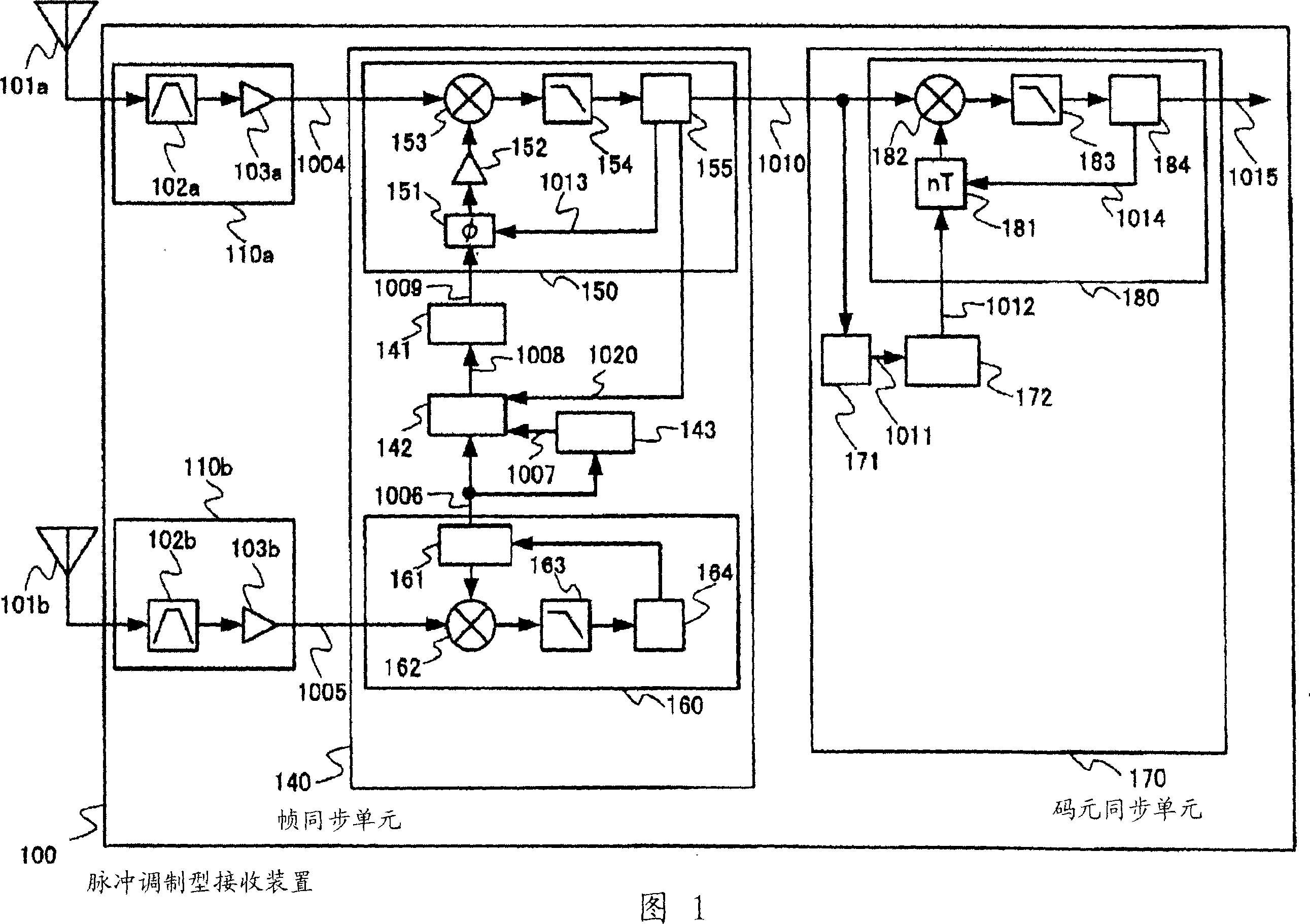
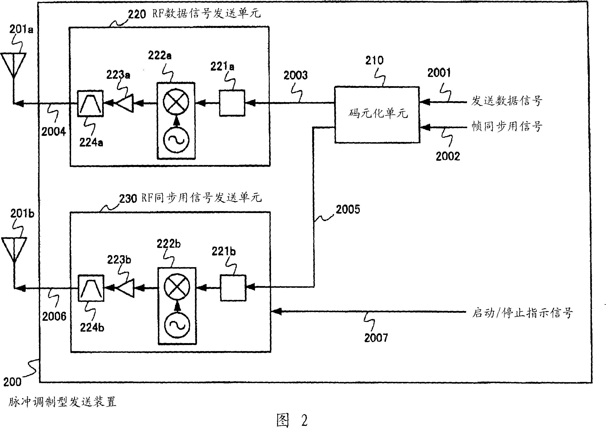
[0070] FIG. 1 is a block diagram showing a synchronous operation of a pulse modulation type receiver according to Embodiment 1 of the present invention. 2 is a block diagram related to the transmission data and frame synchronization signal transmission operation of the pulse modulation type transmission device...

Example Embodiment

[0148] Moreover, by performing low-precision synchronization with the second RF input signal, high-precision synchronization is performed with the first RF input signal, such as performing rough synchronization (rough synchronization) in a communication system and a communication mode with a lower rate. Higher communication systems and communication methods perform high-precision synchronization, thereby reducing the power consumption of the synchronization circuit, and by performing rough synchronization at constant time intervals, it is possible to shorten the time from the start of high-precision synchronization to the establishment of synchronization. (Embodiment 2)

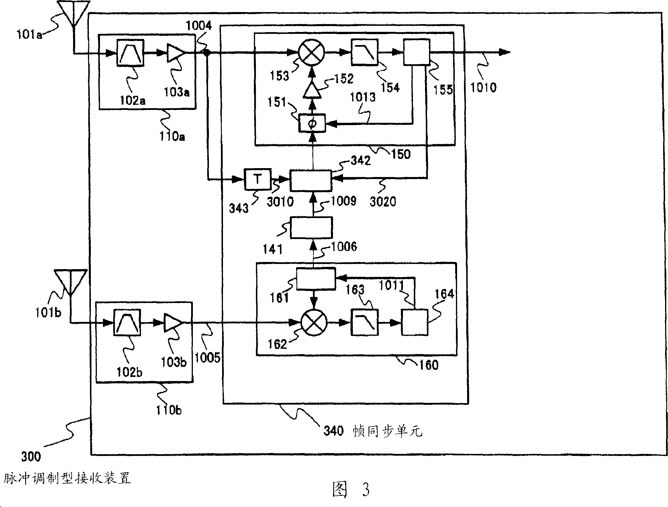
[0149] Next, a pulse modulation type transmission device and a pulse modulation type reception device according to Embodiment 2 of the present invention will be described. The difference from the first embodiment is that the pulse modulation type receiving device is different, but the pulse modulation type tr...

Example Embodiment

[0160] (Embodiment 3)

[0161] Next, a pulse modulation type transmission device and a pulse modulation type reception device according to Embodiment 3 of the present invention will be described. The difference from the second embodiment is that the pulse modulation type receiving device is different, but the pulse modulation type transmitting device is the same as the first embodiment. The functional block configuration of the pulse modulation type receiving apparatus according to Embodiment 3 of the present invention is shown in FIG. 4 .

[0162] FIG. 4 is a functional block diagram of a pulse modulation type receiving apparatus having a frame synchronization unit 440 which receives an RF data signal 1004 in synchronization introduction and establishment of synchronization. The difference between the pulse modulation type receiving device 400 and the pulse modulation type receiving device of FIG. 3 is that the pulse modulation type receiving device 400 is not connected to t...


PUM


Abstract

The aim of the present invention is to provide a pulse modulation type transmitter apparatus and a pulse modulation type receiver apparatus, wherein both a fast synchronization establishment and a low power consumption of a synchronizing part can be achieved at the same time and wherein the data transmission/reception can be performed soon after a commencement of communication, and further a fast data transmission and a low power consumption can be achieved. A first template signal (1006), which is generated based on a separately transmitted RF frame synchronization signal (1005), is used to generate a frame synchronization signal (1009), and a second frame synchronization timing adjusting part (150) is used to synchronize the frame synchronization signal (1009) with a received RF data signal (1004). Then, a synchronization detection is performed, whereby a prompt pulse acquisition and a prompt pulse phase acquisition can be achieved. After the establishment of frame synchronization, a template switching part (142) is used to switch from the first template signal (1006) to a second template signal (1007) that has been already synchronized with the first template signal (1006). Then, a synchronization detection is performed, whereby the frame synchronization can be maintained.

Description

technical field [0001] The present invention relates to a wireless communication device using a pulse-shaped modulation signal. Background technique [0002] In addition to the rapid spread of wireless LAN equipment represented by IEEE802.11b, it is expected that a seamless network society will be established through the mutual wireless connection of AV equipment and / or personal computers. The technology of data communication devices becomes an urgent task. [0003] As one of these technologies, pulse wireless communication using a pulse-shaped modulation signal has attracted attention. As a conventional method for synchronizing received data signals in impulse wireless communication devices, a method of synchronizing by correlation between a signal at a reference time and each signal subjected to forward or backward delay processing is known. known (for example, refer to Patent Document 1). [0004] FIG. 12 is a block diagram showing the configuration of a conventional p...

Claims


Application Information

Patent Timeline
IPC IPC(8): H04L7/08H04L7/00H04L25/49H04J13/00H04B1/7183H04J3/06
Inventor 藤田卓三村政博高桥和晃国枝贤德植木纪行
Owner PANASONIC CORP
Why Eureka
Try Eureka