Electronic information signal transmission enhancement method

A signal transmission and electronic information technology, applied in the field of electronic information transmission, can solve the problems of reducing the quality and stability of information signal transmission, affecting the receiver's reception of signals, and unable to gather electromagnetic waves, so as to improve the transmission quality and stability, maintain quality, the effect of reducing the loss of the signal

Inactive Publication Date: 2021-07-27
深圳沐沐森科技有限公司
View PDF2 Cites 0 Cited by
  • Summary
  • Abstract
  • Description
  • Claims
  • Application Information

AI Technical Summary

Problems solved by technology

[0003] Chinese patent CN106559052A discloses an electronic information transmission amplifier, the electronic information signal is input into the first-stage amplifier circuit through the signal input circuit, after being adjusted by the gain adjustment circuit, it is amplified by the second-stage amplifier circuit, and then output through the output circuit. The weak signal is amplified to increase the gain, thereby increasing the transmission distance of information, easy to use, and has the value of popularization and application; Chinese patent CN106412382A discloses an electronic information signal processing system. When building a data acquisition system with DSP and CPLD, no external connection is required. The professional image acquisition chip avoids complex hardware design and provides sufficient processing capacity; there is a serious problem in the existing electronic information signal enhancement that it cannot effectively gather electromagnetic waves during use, which will affect the The reception of the signal by the receiver will reduce the transmission quality and stability of the information signal

Method used


Image

  • Electronic information signal transmission enhancement method
  • Electronic information signal transmission enhancement method
  • Electronic information signal transmission enhancement method

Examples


Embodiment Construction

[0022] The following will clearly and completely describe the technical solutions in the embodiments of the present invention with reference to the accompanying drawings in the embodiments of the present invention. Obviously, the described embodiments are only some, not all, embodiments of the present invention. Based on the embodiments of the present invention, all other embodiments obtained by persons of ordinary skill in the art without making creative efforts belong to the protection scope of the present invention.

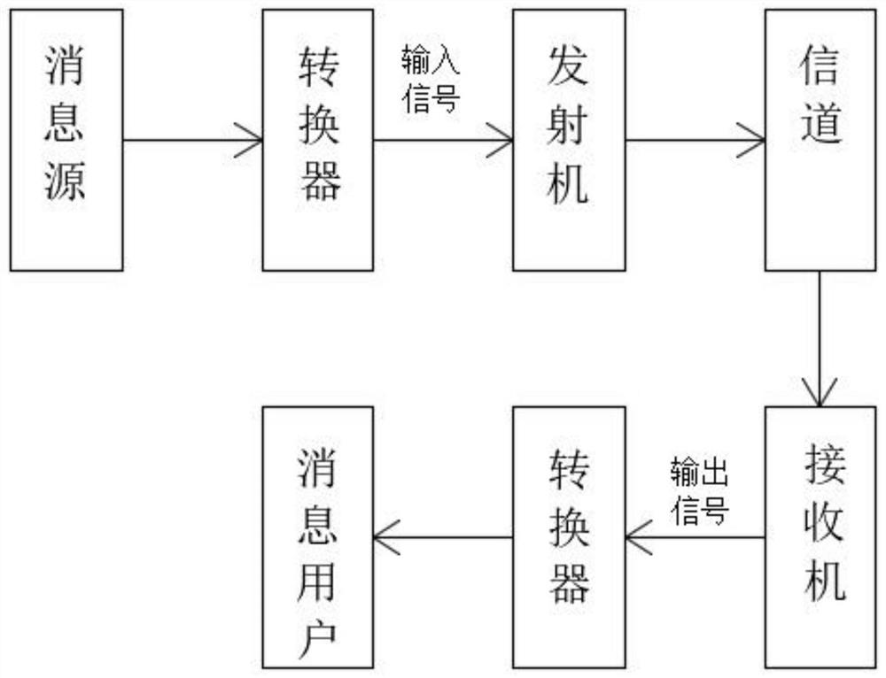
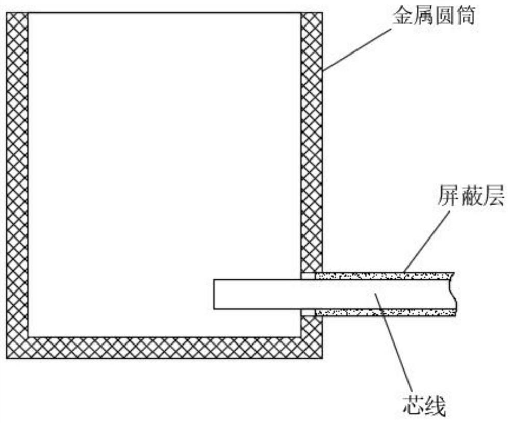
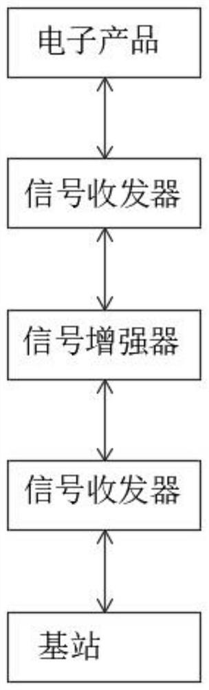
[0023] The present invention provides such as Figure 1-2 A method for enhancing electronic information signal transmission shown, the steps are as follows:

[0024] S1: Making equipment: Find a metal cylinder, cut it vertically with a blade according to the length and position of the existing antenna of the wireless router, and leave a bottom surface for easy fixing;

[0025] S2: Calculate the focus position: according to the calculation formula: F=DxD / 16H (...


PUM


Abstract

The invention discloses an electronic information signal transmission enhancement method. The method comprises the following steps of S1, manufacturing a device, namely finding a metal cylinder, vertically cutting the metal cylinder by using a blade according to the length and the position of an existing antenna of a wireless router, and leaving a bottom surface to facilitate fixation; S2, calculating a focus position according to a calculation formula: F = DxD / 16H (m), wherein D is the diameter of the paraboloid, H is the depth of the paraboloid, and the unit is m; carrying out appropriate movement according to actual conditions, and finding an optimal position point; and measuring by means of software of a wireless network card. A regular metal paraboloid is placed around an existing antenna, the original antenna of the wireless router is modified into a gain antenna with a better effect, the antenna is located at an internal reflection focus of the paraboloid, and energy concentration is formed at the focus through electromagnetic wave reflection, so that the receiving and transmitting of electromagnetic signals are enhanced, signals are enhanced in a specific direction, and further the transmission quality and stability of the electronic information signals are improved.

Description

technical field [0001] The invention relates to the technical field of electronic information transmission, in particular to a method for enhancing electronic information signal transmission. Background technique [0002] Electronic signals are transmitted in the form of electrons or holes in the conductive medium, and transmitted in space using electromagnetic waves (infrared rays are also electromagnetic waves). Analog signals use a combination of voltage amplitude and frequency to express information. For example, in the analog signal that controls the picture tube in the display, the information of vertical synchronization, frame synchronization and color is indicated by the magnitude of voltage and different frequencies. The digital signal is very simple, consisting of two states of "0" and "1": higher than a certain voltage value is considered "1", and lower than a certain voltage value is considered "0", which is the basis of computer information processing , the bas...

Claims


Application Information

Patent Timeline
Patent Type & Authority Applications(China)
IPC IPC(8): H01Q15/16H01Q1/00H01Q1/52H01Q1/50H01Q1/36H01Q1/22
CPCH01Q1/002H01Q1/22H01Q1/36H01Q1/50H01Q1/526H01Q15/16
Inventor 何森兴汤志雄谭毅彬林冰
Owner 深圳沐沐森科技有限公司
Why Eureka
Try Eureka