Computer case

A computer and chassis technology, applied in the field of computer accessories, can solve problems such as chip heat cannot be transmitted, poor heat dissipation effect, and affect computer work, so as to prevent dust from entering the chassis, improve heat dissipation efficiency, and double the air cooling effect Effect

Inactive Publication Date: 2018-05-01
CHANGZHOU COLLEGE OF INFORMATION TECH
View PDF5 Cites 3 Cited by
  • Summary
  • Abstract
  • Description
  • Claims
  • Application Information

AI Technical Summary

Problems solved by technology

Because the increase in temperature will affect the work of various components in the computer, it is necessary to add a cooling device to reduce the temperature of the computer. However, at present, an exhaust device is installed in the chassis, and the exhaust device is used to dissipate heat from the chips in the computer. However, with this method of heat dissipation, although the exhaust device blows air to the chip, the heat in the chip cannot be transmitted, which leads to poor heat dissipation effect, easy to cause damage to the chip, and affect the work of the computer

Method used


Image

  • Computer case
  • Computer case
  • Computer case

Examples


Embodiment 1

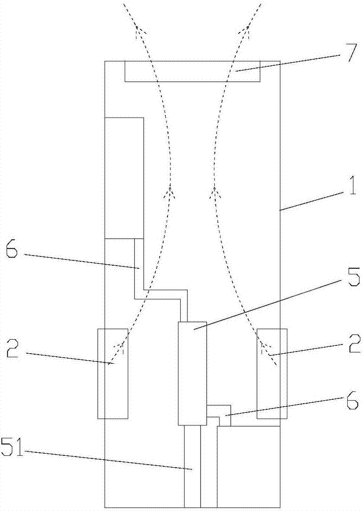
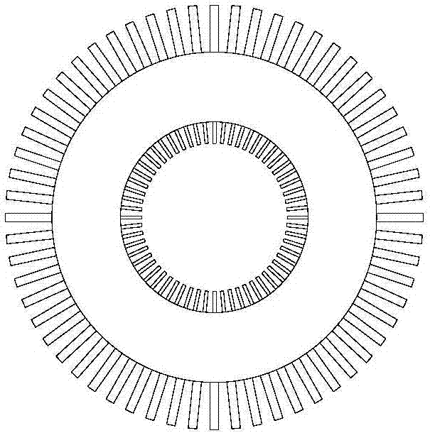
[0026] Embodiment 1: refer to figure 1 , image 3 , Figure 8 , computer case, including case 1, the front side of case 1 is a hard disk module area, the upper end of case 1 is a power module area, the rear side of case 1 is a main board area, and the corresponding case 1 at the main board area is provided with an air extraction device, the air extraction device includes Two exhaust fans 2, a temperature sensor 3, and a controller 4, the controller 4 is fixed on the inner wall of the chassis 1, the temperature sensor 3 is connected to the controller 4, and the controller 4 is connected to control the exhaust fan, the controller 4 adopts MCU, and the two exhaust fans The air fan 3 is arranged on the chassis 1 corresponding to the lower side of the main board area, and the two exhaust fans 2 are arranged opposite to each other along the width direction of the chassis 1. The exhaust fans 2 draw fresh air into the chassis 1, and the two exhaust fans 2 correspond to the chassis. ...

Embodiment 2

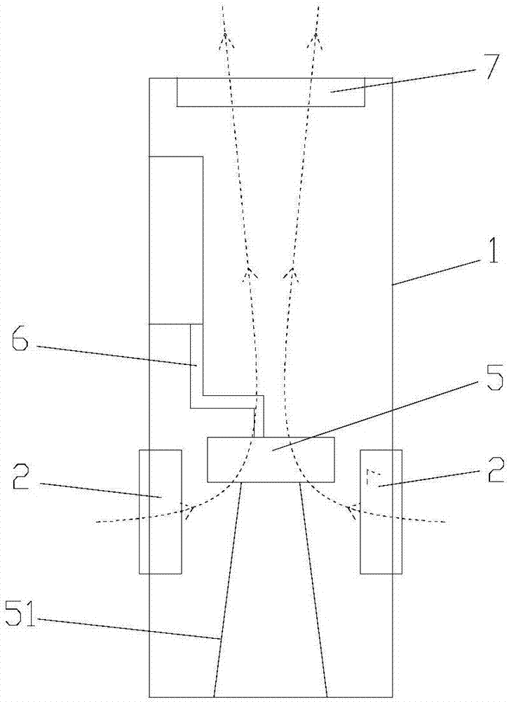
[0028] Embodiment 2: refer to figure 2 , image 3 , Figure 8, computer case, including case 1, the front side of case 1 is a hard disk module area, the upper end of case 1 is a power module area, the rear side of case 1 is a main board area, and the corresponding case 1 at the main board area is provided with an air extraction device, the air extraction device includes Two exhaust fans 2, a temperature sensor 3, and a controller 4. The controller 4 adopts an MCU. The two exhaust fans 3 are arranged on the chassis 1 corresponding to the lower side of the main board area, and the two exhaust fans 2 are along the width direction of the chassis 1. Relatively arranged, the exhaust fan 2 draws in fresh air into the chassis 1, and the two exhaust fans 2 are connected to the corresponding parts of the chassis by screws, and an annular cooling disc 5 is arranged between the two exhaust fans, and the cooling disc 5 is placed horizontally to dissipate heat. The inner and outer walls ...


PUM


Abstract

The invention belongs to the technical field of computer accessories, and particularly relates to a computer case. The computer case comprises a case; two opposite air extractors are arranged on two opposite walls of the case; a temperature sensing element and a controller are arranged in the case; the temperature sensing element is connected with the controller; the controller is connected with the air extractors and is used for controlling the air extractors; a cooling plate is arranged between the two air extractors; the cooling plate is connected with a heating element in the case througha heat conduction fin; air exhaustion devices are arranged on corresponding case walls above the air extractors; the air exhaustion devices are connected with the controller; ventilation port structures are arranged at positions, corresponding to the air extractors and the air exhaustion devices, on the case walls; and dustproof mechanisms are arranged at the ventilation port structures to rapidlytransfer heat in the case to the outside, so as to improve the cooling efficiency and prolong the service life of computers.

Description

technical field [0001] The invention belongs to the technical field of computer accessories, and in particular relates to a computer case. Background technique [0002] In the existing technology, when the computer is working, the dust inside the case generates high temperature. With the continuous progress and continuous upgrading of computer technology, the integrated circuits of the computer are becoming more and more sophisticated and smaller and smaller. Because the increase in temperature will affect the work of the various components in the computer, it is necessary to add a cooling device to reduce the temperature of the computer. But adopt this method to dissipate heat, although the exhaust device blows the air to the chip, the heat in the chip cannot be transferred out, which leads to poor heat dissipation effect, easily causes damage to the chip, and affects the work of the computer. Contents of the invention [0003] The technical problem to be solved by the p...

Claims


Application Information

Patent Timeline
Patent Type & Authority Applications(China)
IPC IPC(8): G06F1/20G06F1/18
CPCG06F1/183G06F1/20G06F2200/202
Inventor 郭明
Owner CHANGZHOU COLLEGE OF INFORMATION TECH
Why Eureka
Try Eureka