Oblique pole type motor Hall installation structure

A technology of installation structure and sloping pole, applied in the direction of electromechanical devices, structural connections, electrical components, etc., can solve the problems of difficult control of the external angle calculation and adjustment of the Hall, unstable motor motion, accurate positioning and fixation of the Hall, etc. Achieve the effect of improving motor motion stability, reducing motor cost, and accurate positioning and fixing

Pending Publication Date: 2018-05-01
HENGDIAN GRP INNUOVO ELECTRIC
View PDF0 Cites 2 Cited by
  • Summary
  • Abstract
  • Description
  • Claims
  • Application Information

AI Technical Summary

Problems solved by technology

[0002] Existing Halls are externally installed, so a special induction magnet needs to be assembled, which will cause an increase in unbalance, and the calculation and adjustment of the external angle of the Hall are difficult to control, and it is difficult to make the Hall’s The positioning and fixing are more accurate, making the motor movement unstable

Method used


Image

  • Oblique pole type motor Hall installation structure
  • Oblique pole type motor Hall installation structure

Examples


Embodiment Construction

[0012] The present invention will be further described below according to the accompanying drawings and specific embodiments.

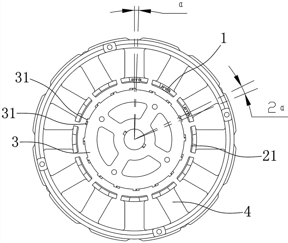
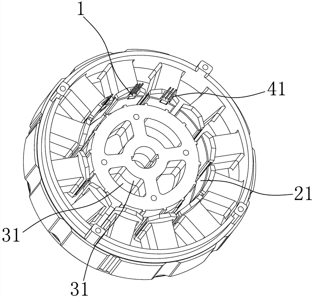
[0013] Depend on figure 1 , figure 2 As shown in the present invention, a hall installation structure of a slanted-pole motor is provided. The hall 1 is fixed on the stator, and the stator is provided with a rotor 3. The rotor 3 is composed of two rotor units 31, and the adjacent rotor units 31 are opposite to each other. Deflection, the inner edge of the tooth portion 21 of the stator is formed with an accommodating groove for accommodating the Hall 1, the Hall housing of the Hall 1 is located in the accommodating groove, and the Hall pins of the Hall 1 extend along the parallel line of the rotor shaft, The center of the accommodating slot deviates from the center of the stator tooth portion where the accommodating slot is located, the relative deflection angle of the adjacent rotor units 31 is 2α, and the relative deflection angle between the cent...


PUM


Abstract

The invention aims to provide an oblique pole type motor Hall installation structure which can be used for achieving a built-in Hall and more accurate installation position of the Hall and reducing unbalancing quantity. In order to achieve the purpose, the oblique pole type motor Hall installation structure employs the following technical scheme that the Hall is fixed on a stator, a rotor is arranged in the stator and comprises multiple segments of single rotors, adjacent single rotors deviate relative to each other, an accommodating groove is formed in an inner edge of a tooth part of the stator and is used for accommodating the Hall, a Hall shell of the Hall is arranged in the accommodating groove, a Hall pin of the Hall extends along a parallel line of a rotor shaft, and a center of theaccommodating groove deviates from the center of the tooth part of the stator wherein the accommodating groove is located.

Description

technical field [0001] The invention relates to a Hall mounting structure of an oblique pole type motor. Background technique [0002] The existing Halls are external, so a special induction magnetic steel needs to be installed, which will increase the unbalance, and the calculation and adjustment of the external angle of the Hall are difficult to control. The positioning and fixing are more accurate, which makes the motor movement unstable. SUMMARY OF THE INVENTION [0003] The purpose of the present invention is to provide a slanted pole type motor hall installation structure that can realize the built-in hall, the installation position of the hall is more accurate, and the unbalance amount is reduced. [0004] In order to achieve the above purpose, the present invention adopts the following technical scheme: a hall installation structure of a slanted pole motor, the hall is fixed on the stator, and a rotor is arranged in the stator, and the rotor is composed of a multi...

Claims


Application Information

Patent Timeline
Patent Type & Authority Applications(China)
IPC IPC(8): H02K11/215
CPCH02K11/215
Inventor 吴凌云
Owner HENGDIAN GRP INNUOVO ELECTRIC
Why Eureka
Try Eureka