Rapid changeover clamp of industrial robot

An industrial robot, quick-change technology, applied in the direction of manufacturing tools, chucks, manipulators, etc., can solve the problems of untimely replacement of fixtures, falling clamping force, and industrial robot quick-change fixtures without a clamping force detection mechanism. , to achieve the effect of high connection efficiency and improved security

Inactive Publication Date: 2018-05-04
孟宪洪
View PDF0 Cites 2 Cited by
  • Summary
  • Abstract
  • Description
  • Claims
  • Application Information

AI Technical Summary

Problems solved by technology

[0002] In the prior art, the quick-change clamps of industrial robots have a complicated connection structure, and the connection and disassembly speeds are sl

Method used


Image

  • Rapid changeover clamp of industrial robot
  • Rapid changeover clamp of industrial robot
  • Rapid changeover clamp of industrial robot

Examples


specific Embodiment approach

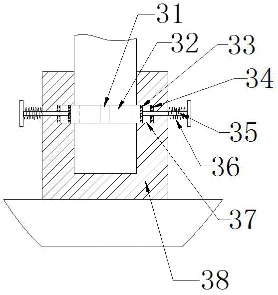
[0023] The specific embodiment: when the staff installs this device, the circuit between the electromagnet 34 and the external power supply is connected, and the electromagnet 34 is energized to generate magnetism, so that the electromagnet 34 generates a magnetic attraction force to the magnet ring 33, thereby making the magnet ring 33 to The electromagnet 34 moves in the direction, the magnet ring 33 moves to drive the clamp ring 32 to move, the clamp ring 32 moves to drive the guide rod 35 to move, and the guide rod 35 moves to generate a tensile force on the spring one 36, so that the spring one 36 is stretched, and the clamp ring 32 moves When reaching the inside of the annular groove 2 37, the staff assembles the connecting cylinder 38 to the lower end of the boom 2, and moves the connecting cylinder 38 along the boom 2. , the circuit between the electromagnet 34 and the external power supply is disconnected, so that the electromagnet 34 loses its magnetism, and under the...


PUM


Abstract

The invention provides a rapid changeover clamp of an industrial robot. The rapid changeover clamp comprises an annular groove 1, a clamping ring, a guide rod, an annular groove 2, a connecting cylinder, T-shaped sliding grooves, T-shaped sliders, a carrier plate and a push rod, wherein the annular groove 2 is formed in the inner annular side surface of the connecting cylinder, the right end of the clamping ring is assembled in the annular groove 2, and the left end of the clamping ring is assembled in the annular groove 1; and the left end of the guide rod is fixed at the right end of the annular side surface of the clamping ring, and the right end of the guide rod penetrates through the connecting cylinder and extends to the right side of the connecting cylinder. The design is convenientfor the connection of the device. The T-shaped sliders are symmetrically fixedly arranged at the left and right sides of the rear side surface of the carrier plate, the T-shaped sliders are assembledin the T-shaped sliding grooves, the T-shaped sliding grooves are formed in the front end surface of the clamp body, and the rear end of the push rod penetrates through the carrier plate and extendsto the rear side of the carrier plate. The design realizes the detection of the clamping force of the clamp body. The rapid changeover clamp is convenient to use and convenient to connect, realizes afunction of detecting clamping force, and is great in safety and high in reliability.

Description

technical field [0001] The invention relates to a quick-change clamp for an industrial robot, which belongs to the field of industrial machinery and equipment. Background technique [0002] In the prior art, the quick-change clamps of industrial robots have a complicated connection structure, and the connection and disassembly speeds are slow; Untimely replacement of fixtures may cause the clamping force to drop, so a quick-change fixture for industrial robots is needed to solve the above problems. Contents of the invention [0003] Aiming at the deficiencies in the prior art, the purpose of the present invention is to provide a quick-change clamp for industrial robots to solve the problems raised in the above-mentioned background technology. The present invention is easy to use, easy to connect, realizes the function of clamping force detection, and is safe Good performance and high reliability. [0004] In order to achieve the above object, the present invention is ach...

Claims


Application Information

Patent Timeline
IPC IPC(8): B25J15/04
CPCB25J15/04B25J15/0441
Inventor 孟宪洪
Owner 孟宪洪
Why Eureka
Try Eureka