
A Guidance Law Design Method for UAV Path Following Control

A technology of path tracking and design method, applied in vehicle position/route/altitude control, control/regulation system, non-electric variable control, etc. slow effect

Active Publication Date: 2021-01-19
SHANGHAI RADIO EQUIP RES INST
View PDF7 Cites 0 Cited by
  • Summary
  • Abstract
  • Description
  • Claims
  • Application Information

AI Technical Summary

Problems solved by technology

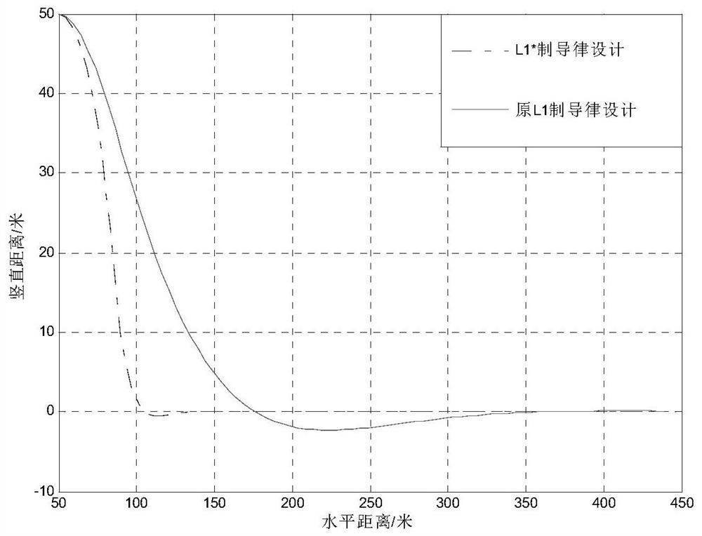
[0005] The purpose of the present invention is to provide a guidance law design method for UAV path tracking control, which can solve the problem that the tracking rate is too slow in the tracking control in the prior art

Method used


Image

  • A Guidance Law Design Method for UAV Path Following Control
  • A Guidance Law Design Method for UAV Path Following Control
  • A Guidance Law Design Method for UAV Path Following Control

Examples


Embodiment Construction

[0033] The present invention will be further elaborated below by describing a preferred specific embodiment in detail in conjunction with the accompanying drawings.

[0034] Such as Figure 5 Shown, the present invention proposes a kind of guidance law design method of unmanned aerial vehicle path following control, and it comprises the following steps:

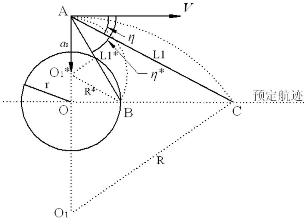
[0035] S1. The flight speed of the UAV is V, and the initial position A of the UAV is projected to the predetermined track, and the projected point is taken as O, and the distance between the flight track of the UAV and the predetermined track is recorded as the eccentricity d;

[0036] In this example, if figure 1 As shown, the UAV is flying to the right at a constant speed V=10m / s, the initial position is recorded as A, the predetermined track is a straight-line path, and the projected point from point A to the predetermined trajectory is marked as O, and the flight trajectory of the UAV is in line with The distance betwe...


PUM


Abstract

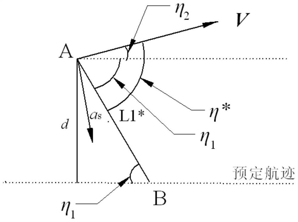
The invention discloses a guidance law design method for unmanned aerial vehicle path tracking control. The method includes the following steps that S1, the flying speed of an unmanned aerial vehicleis V, projection is conducted on a preset track from the initial position A of the unmanned aerial vehicle, a projection point is marked as O, and the distance between the flying path of the unmannedaerial vehicle and the preset track is marked as d; S2, a circle with the radius being r is obtained with the projection point as the circle center, the intersection point of the circle and the presettrack in front of the unmanned aerial vehicle speed direction is marked as B, the length of AB is marked as L1*, and a L1* guidance law is designed with the point B as a reference point; S3, a reference circle O1* with the radius being R* is selected, and an unmanned aerial vehicle lateral acceleration instruction as* is calculated by using centripetal acceleration and motion geometrical relationship. The method has the advantage that the problem that the tracking speed is too low in tracking control in the prior art can be solved.

Description

technical field [0001] The invention relates to the technical field of unmanned aerial vehicles, in particular to a guidance law design method for path tracking control of unmanned aerial vehicles. Background technique [0002] UAVs can carry a variety of electronic equipment loads instead of traditional piloted aircraft to perform various complex and dangerous tasks. Its broad application prospects and adaptability to complex tasks have made it a key field of research at home and abroad in recent years. UAV path tracking control is one of the important technologies of UAV flight control. It means that the UAV tracks an expected trajectory that meets the flight requirements and performance constraints to complete the scheduled flight mission. The performance of tracking control directly affects the flight stability. performance, safety and economy. [0003] In the UAV path tracking control problem, it is necessary to design the guidance law, that is, to design the expected ...

Claims


Application Information

Patent Timeline
Patent Type & Authority Patents(China)
IPC IPC(8): G05D1/10
CPCG05D1/0088G05D1/101
Inventor 郑黎明周启航赵桂军夏峥黄海涛
Owner SHANGHAI RADIO EQUIP RES INST
Learn More