A Non-uniformity Correction Method of Infrared Image Based on Scene Frame Registration

A non-uniformity correction and infrared image technology, applied in image enhancement, image data processing, instruments, etc., can solve problems such as image degradation, failure to obtain good image quality, slow convergence rate, etc., to save time, good correction effect, The effect of fast convergence rate

Inactive Publication Date: 2018-12-14
NANJING UNIV OF SCI & TECH
View PDF2 Cites 0 Cited by
  • Summary
  • Abstract
  • Description
  • Claims
  • Application Information

AI Technical Summary

Problems solved by technology

[0006] The purpose of the present invention is to provide an infrared image non-uniformity correction method based on scene frame registration, which solves the problem of severe image degradation when the image is still, the slow convergence rate, and the inability to obtain a good image when the non-uniformity is strong. quality problem

Method used


Image

  • A Non-uniformity Correction Method of Infrared Image Based on Scene Frame Registration
  • A Non-uniformity Correction Method of Infrared Image Based on Scene Frame Registration
  • A Non-uniformity Correction Method of Infrared Image Based on Scene Frame Registration

Examples


Embodiment 1

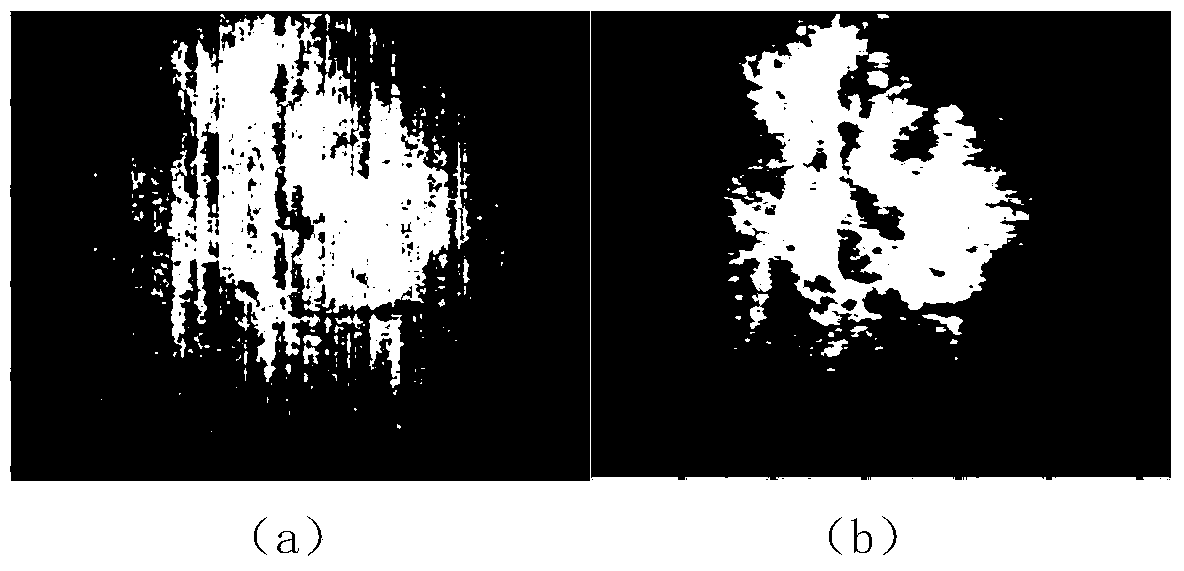
[0056] combine figure 2 , the infrared detector collects the infrared image of the mountain at night at high altitude, and the image size is 320×256;

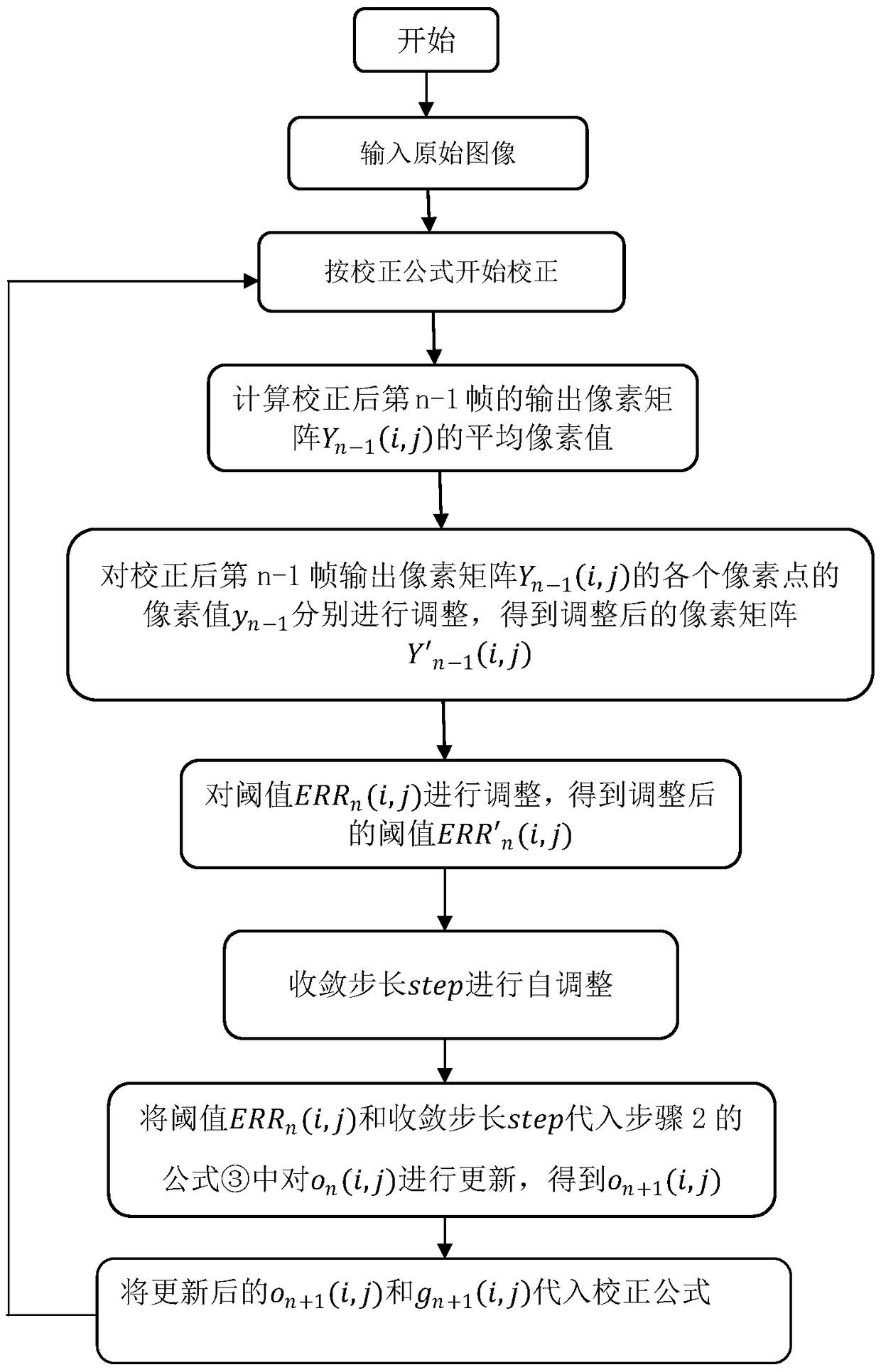
[0057] Step 1. After the original analog image collected by the infrared detector is converted by A / D, the original digital image is obtained;

[0058] Step 2. Correct the original digital image to obtain the output pixel matrix Y of the n-1th frame after correction n-1 (i, j) and the output pixel matrix Y of the nth frame after correction n (i, j), the correction formula is as follows:

[0059]

[0060] Step 3. Determine the output pixel matrix Y of the n-1th frame after the above correction n-1 The average value of (i, j): the output pixel matrix Y of the n-1th frame after statistical correction n-1 (i, j), and find its average average n , n represents the frame number;

[0061] Step 4. Output the pixel matrix Y for the n-1th frame after correction n-1 The pixel value y of each pixel point of (i, j) n-1 Adjust res...

Embodiment 2

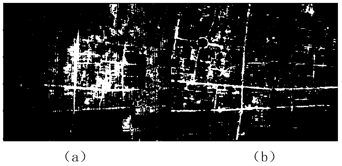
[0080] combine image 3 , the infrared detector collects the infrared image of the overpass shot at night at high altitude, and the image size is 320×256;

[0081] Step 1. After the original analog image collected by the infrared detector is converted by A / D, the original digital image is obtained;

[0082] Step 2. Correct the original digital image to obtain the output pixel matrix Y of the n-1th frame after correction n-1 (i, j) and the output pixel matrix Y of the nth frame after correction n (i, j), the correction formula is as follows:

[0083]

[0084] Step 3. Determine the output pixel matrix Y of the n-1th frame after the above correction n-1The average value of (i, j): the output pixel matrix Y of the n-1th frame after statistical correction n-1 (i, j), and find its average average n , n represents the frame number;

[0085] Step 4. Output the pixel matrix Y for the n-1th frame after correction n-1 The pixel value y of each pixel point of (i, j) n-1 Adjust ...


PUM


Abstract

The invention discloses an infrared image non-uniformity correction method based on scene inter-frame registration. The method comprise following steps: obtaining an original digital image by performing A / D conversion to an original simulation image acquired by an infrared detector; then performing correction to the original digital image to obtain an output pixel matrix Yn-1(i, j) of a corrected (n-1)th frame and an output pixel matrix Yn(i, j) of a corrected nth frame; performing statistics to the output pixel matrix Yn-1(i, j) of the corrected (n-1)th frame and obtaining its average value averagen; finally, performing updating to o<n+1>(i, j) and g<n+1>(i, j) through the self-adjusting of the output pixel matrix Yn-1(i, j) of the corrected (n-1)th frame, the threshold value ERRn(i, j), and the convergence step length step to achieve non-uniformity correction of the whole image. The method is simple and efficient; convergence rate is high; highly non-uniform images can be corrected by the method; good correction effect can be achieved by the method in different scenes; the method has broad application.

Description

technical field [0001] The technology of the invention belongs to the field of infrared image non-uniformity correction, and in particular relates to an infrared image non-uniformity correction method based on registration between scene frames. Background technique [0002] Infrared radiation enables human beings to expand their vision of nature. In the infrared imaging system, external infrared radiation is transmitted to the infrared detector through the optical system and focused on the thermal sensor. The detector converts the infrared radiation energy into an electrical signal. The signal reflects the intensity of infrared radiation energy, and after amplification, AD sampling and signal processing, an observable infrared image is formed on the display system. [0003] The infrared imaging system uses the difference in surface temperature of the object for imaging. The response of the front-end detector is not absolutely linear, but generally increases with the increas...

Claims


Application Information

Patent Timeline
Patent Type & Authority Patents(China)
IPC IPC(8): G06T5/00
Inventor 隋修宝匡小冬陈钱顾国华钱毅涛赵耀陶远荣刘源潘科辰沈雪薇
Owner NANJING UNIV OF SCI & TECH
Why Eureka
Try Eureka