Transmission rotating nut spanner

A technology of rotating nut and driving nut, applied in the field of wrench, can solve the problems of inconvenient use, inconvenient disassembly, time-consuming and labor-intensive, etc., and achieve the effect of convenient disassembly and quick disassembly

Inactive Publication Date: 2018-05-08
龙伟
View PDF4 Cites 1 Cited by
  • Summary
  • Abstract
  • Description
  • Claims
  • Application Information

AI Technical Summary

Problems solved by technology

[0002] At present, after assembly and modification of many devices, especially during the debugging process, the device will be moved, and the screws on the device are inconvenient to disassemble because they are at the bottom or blocked by other devices, and when installing the screws, usually It needs to be installed in order. Once it is found to be unsatisfactory during debugging and needs to be disassembled, it must be disassembled one by one in order. It is inconvenient to use and time-consuming. Therefore, it is necessary to design an easy-to-use and separate Wrench for removing position-specific screws

Method used


Image

  • Transmission rotating nut spanner
  • Transmission rotating nut spanner
  • Transmission rotating nut spanner

Examples


specific Embodiment 1

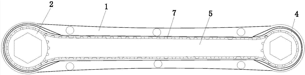
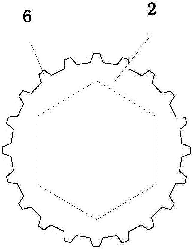
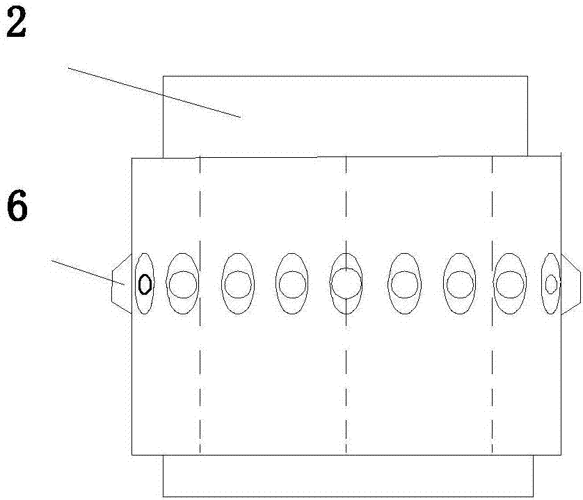
[0026] refer to figure 1 , 2 , 3, 4, 5, 6 and 10 shown in a transmission rotary nut wrench, including a housing 1 and a double-nut transmission mechanism arranged in the inner cavity of the housing 1, the double-nut transmission mechanism includes two transmission nuts 2 , two drive nuts 2 are respectively arranged at both ends of the inner cavity of the housing 1, and a transmission device for connecting the two drive nuts 2 is arranged between the two drive nuts 2, and the inner rings of the two drive nuts 2 The projected shape in its own axial direction is a regular hexagon, and the two ends of the housing 1 respectively correspond to the position of the drive nut 2. There is a circular through hole 3 penetrating through the housing 1, and the two circular through holes 3 are located on the The corresponding drive nuts 2 are coaxial.

[0027] Both ends of the housing 1 are provided with a nut accommodation chamber 4 for accommodating the transmission nut 2, and the two nu...

specific Embodiment 2

[0032] refer to Figure 7 , 8 A kind of transmission rotating nut wrench shown in , 9 and 10, comprises housing 1 and the double-nut transmission mechanism that is arranged on housing 1 cavity, and described double-nut transmission mechanism comprises two drive nuts 2, two drive nuts 2 They are respectively arranged at both ends of the inner cavity of the housing 1, and a transmission device for connecting the two transmission nuts 2 is arranged between the two transmission nuts 2, and the inner rings of the two transmission nuts 2 are arranged in the The projection shapes are all regular hexagons, and the two ends of the housing 1 respectively correspond to the positions of the transmission nuts 2. A circular via hole 3 penetrating through the housing 1 is provided. axis.

[0033] Both ends of the housing 1 are provided with a nut accommodation chamber 4 for accommodating the transmission nut 2, and the two nut accommodation chambers 4 are connected through a transmission c...


PUM


Abstract

The invention relates to the field of spanners, in particular to a transmission rotating nut spanner. The transmission rotating nut spanner comprises a shell and a double-nut transmission mechanism arranged in an inner cavity of the shell. The double-nut transmission mechanism comprises two transmission nuts, wherein the two transmission nuts are arranged at the two ends of the inner cavity of theshell correspondingly, a transmission device used for connecting the two transmission nuts in a transmission manner is arranged between the two transmission nuts, the projections of inner rings of the two transmission nuts in the axial directions of the inner rings are both in a regular hexagon shape. The positions, corresponding to the transmission nuts, of the two ends of the shell are each provided with a round via hole penetrating the shell. The two round via holes and the corresponding transmission nuts are coaxial. By means of the transmission rotating nut spanner, internal screws shielded by equipment can be conveniently dismounted, meanwhile, two transmission manners can be flexibly selected, using is convenient, and time and labor are saved.

Description

technical field [0001] The invention relates to the field of wrenches, in particular to a transmission rotary nut wrench. Background technique [0002] At present, after assembly and modification of many devices, especially during the debugging process, the device will be moved, and the screws on the device are inconvenient to disassemble because they are at the bottom or blocked by other devices, and when installing the screws, usually It needs to be installed in order. Once it is found to be unsatisfactory during debugging and needs to be disassembled, it must be disassembled one by one in order. It is inconvenient to use and time-consuming. Therefore, it is necessary to design an easy-to-use and separate A wrench for removing a screw in a specific location. Contents of the invention [0003] The object of the present invention is to provide a transmission rotary nut wrench to solve the deficiencies of the prior art. [0004] In order to solve the above problems, the p...

Claims


Application Information

Patent Timeline
Patent Type & Authority Applications(China)
IPC IPC(8): B25B17/02
CPCB25B17/02
Inventor 龙伟
Owner 龙伟
Why Eureka
Try Eureka