Garbage grab bucket crane

A technology for cranes and garbage, which is applied in the direction of cranes, trolley cranes, load hanging components, etc., can solve the problems of crane load limit and low work efficiency, and achieve increased cargo capacity, increased grabbing area, and improved The effect of cleaning efficiency

Pending Publication Date: 2018-05-08
浙江邦博机械有限公司
View PDF0 Cites 10 Cited by
  • Summary
  • Abstract
  • Description
  • Claims
  • Application Information

AI Technical Summary

Problems solved by technology

And because most of the garbage is in a fragmented state, the grab bucket is often unable to grab a large amount of garbage at once, the work efficiency is low, and the load capacity of the crane is often limited by the wire rope.

Method used


Image

  • Garbage grab bucket crane
  • Garbage grab bucket crane
  • Garbage grab bucket crane

Examples


Embodiment 1

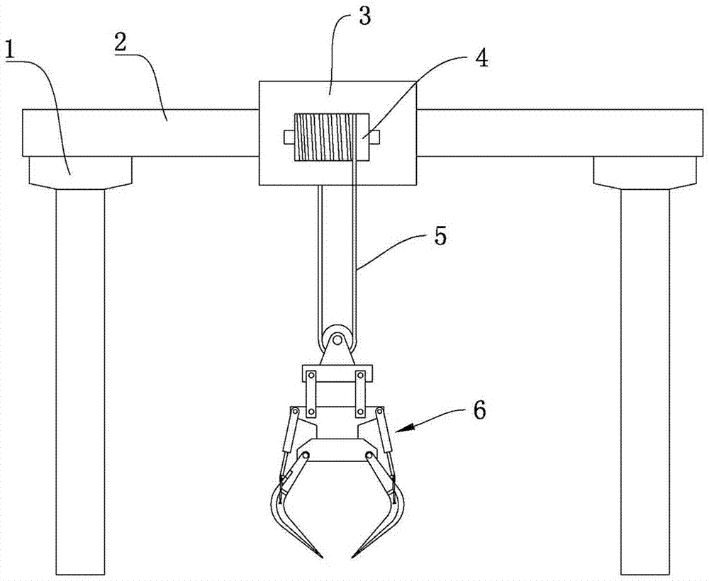
[0022] Embodiment 1: as Figure 1-3 Shown, a kind of rubbish grab crane comprises track beam 1, the main beam 2 that moves along track beam 1, the mobile trolley 3 that moves along main beam 2 and the hoisting device that is installed on the mobile trolley 3, and described hoisting device comprises Lifting reel 4, grab bucket 6 and steel wire rope 5, described lifting drum 4 is installed on the described moving trolley 3, and described steel wire rope 5 is connected between lifting drum 4 and described grab bucket 6,

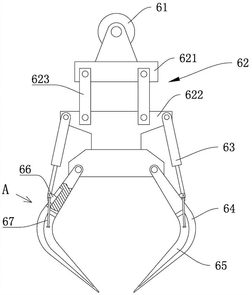
[0023] Such as figure 2 with image 3 As shown, the grab bucket 6 includes a support 62, several claw arms 64 circumferentially distributed on the support 62, and a hydraulic cylinder 63 that pushes a single claw arm 64 to swing. The upper end of the support 62 is provided with a movable pulley 61. One end of the wire rope 5 is wound on the lifting drum 4, and the other end is wound around the movable pulley 61 and fixedly connected to the mobile trolley 3; t...

Embodiment 2

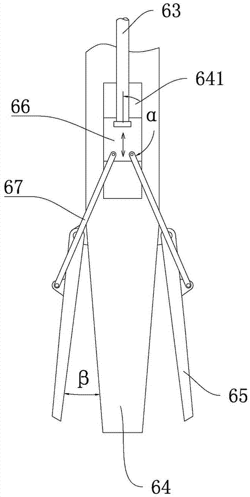
[0025] Embodiment 2: as Figure 4 As shown, the difference from Embodiment 1 is that the slider 66 is a split structure, including a first slider 661 and a second slider 662 arranged up and down, and the first slider 661 and the second slider The block 662 is connected with an elastic piece 663 which makes the two move away from each other, and the elastic piece 663 is a spring. The hydraulic cylinder 63 is hinged on the first slider 661 , and the first connecting rod 67 is hinged on the second slider 662 .

[0026] The first connecting rod 67 includes a hinged first rod body 671 and a second rod body 672, the first rod body 671 is hinged on the side jaw 65, and the second rod body 672 is hinged on the second slider 662 , there is a second connecting rod 68 between the second rod body 672 and the first slider 661, when the second slider 662 moves relative to the first slider 661, the second connecting rod 68 drives the side claw 65 to rotate relative to the claw arm 64 in th...


PUM


Abstract

The invention relates to a garbage grab bucket crane which comprises a track beam, a main beam, a travelling car and a hoisting device, wherein the hoisting device comprises a lifting drum, a grab bucket and a steel wire rope; the grab bucket comprises a support, a claw arm and a hydraulic cylinder; a movable block is arranged at the upper end of the support; one end of the steel wire rope is wound on the lifting drum; the other end of the steel wire rope bypasses the movable block to be fixedly connected onto the travelling car; at least one side of the claw arm is provided with a side claw;a linkage mechanism is arranged between the claw arm and the side claw; the hydraulic cylinder pushes the claw arm to swing through the linkage mechanism and pushes the side claw to swing; and when the claw arm is closed up or stretched out, the side claw is enabled to be stretched out or closed up in the lateral direction of the claw arm. The garbage grab bucket crane increases the grabbing areaof the claw arm and the grabbing amount of the grab bucket; in addition, a fixed pulley mechanism is adopted between the grab bucket and the lifting drum, and part of weight of the grab bucket is dispersed on the travelling car to enable the steel wire rope to bear larger weight, so that the cargo dead weight of the crane is increased, the operating power of the lifting drum is reduced and the garbage cleaning efficiency is improved.

Description

technical field [0001] The invention relates to the technical field of cranes, in particular to a garbage grab crane. Background technique [0002] With the rapid development of modern science and technology, and the improvement of urbanization level, industrial waste and domestic waste are produced in large quantities every year and show an increasing trend, which seriously pollutes the environment. In terms of garbage disposal, handling, mixing, stacking, feeding, etc. are required during the garbage disposal process, and garbage grabs and cranes are often required to carry the garbage. And because most of the garbage is in a fragmented state, the grab bucket often cannot grab a large amount of garbage at once, and the work efficiency is low, and the load capacity of the crane is often limited by the wire rope. Contents of the invention [0003] The object of the present invention is to provide a garbage grab crane, which can increase the amount of garbage picked up and...

Claims


Application Information

Patent Timeline
Patent Type & Authority Applications(China)
IPC IPC(8): B66C19/00B66C3/16
CPCB66C19/00B66C3/16
Inventor 朱晓翔
Owner 浙江邦博机械有限公司
Why Eureka
Try Eureka