Industrial robot connecting base capable of realizing convenient adjustment of angle
An industrial robot and angle adjustment technology, applied in manipulators, manufacturing tools, program-controlled manipulators, etc., can solve the problems of high cost, suitability for industrial robots, complicated and troublesome device design, etc. Effect
- Summary
- Abstract
- Description
- Claims
- Application Information
AI Technical Summary
Problems solved by technology
Method used
Image
Examples
Embodiment 1
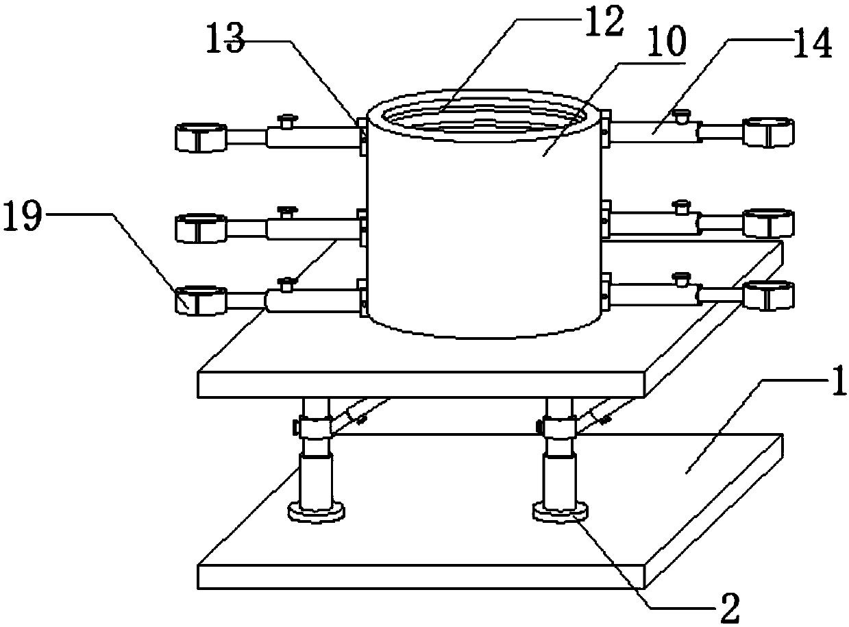
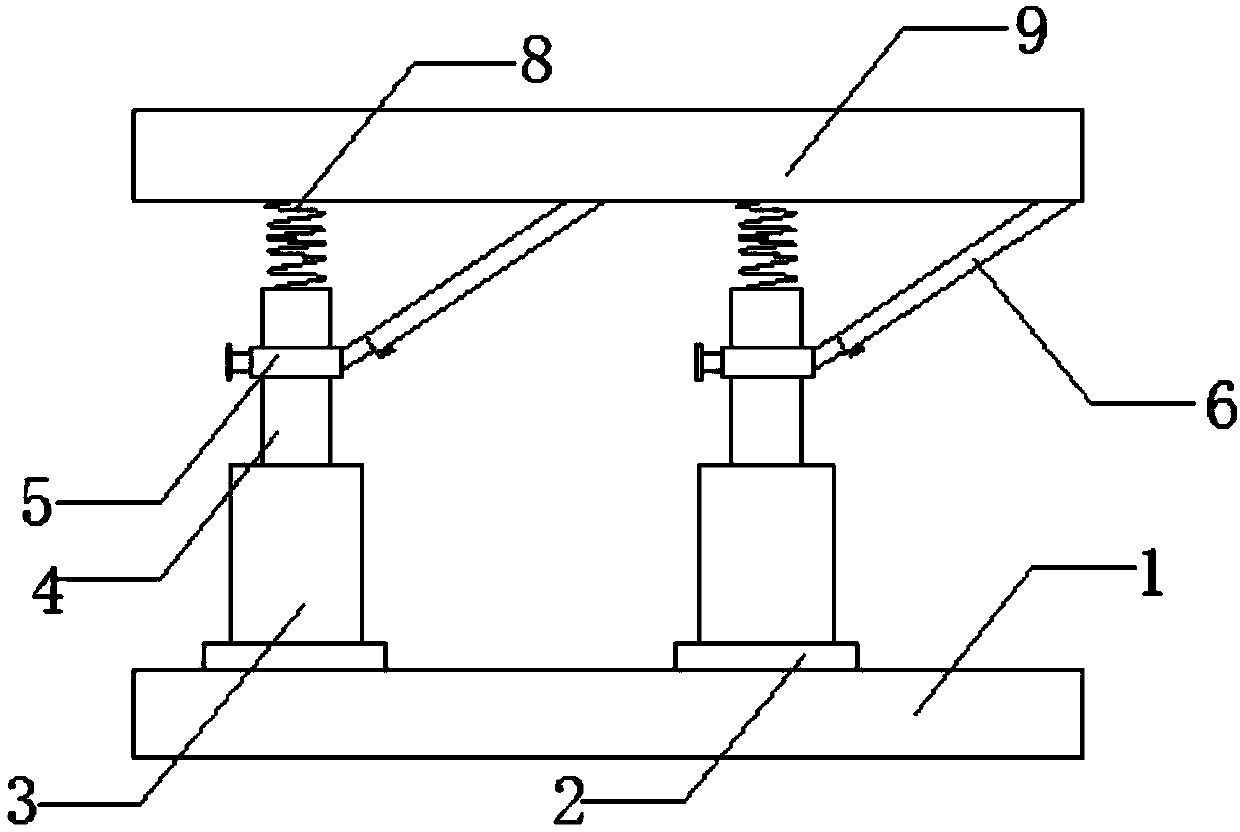
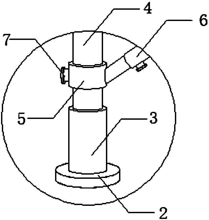
[0025] see Figure 1-5 As shown, an industrial robot connecting base for easy angle adjustment includes a first base 1, a telescopic column 4, a brace 6, a spring 8, a casing 10, a threaded ring 12, a screw 15, an extension rod 17, a shackle 19 and Connecting block 21, two groups of rotating shafts 2 are symmetrically arranged on the first base 1, and shaft columns 3 are arranged on the rotating shafts 2, and telescopic columns 4 are arranged on the shaft columns 3. By setting the telescopic columns 4 and the rotating shafts 2, the telescopic columns 4 The telescopic effect can adjust the height of the base, and through the rotating shaft 2, the direction of the base can be rotated 360 degrees dynamically, giving the industrial robot a variety of possibilities when working, and the outer wall of the telescopic column 4 is covered with Connect with movable sleeve 5, one side wall of movable sleeve 5 is connected with diagonal brace 6, and the top of telescopic column 4 is provi...
Embodiment 2
[0027] read on Figure 1-5 As shown, compared with the above embodiment, the other side wall of the movable sleeve 5 and the side wall of the diagonal brace 6 are clamped with a block 7, and the diameter of the inner wall of the movable sleeve 5 matches the diameter of the telescopic column 4 , There is a flexible connection between the movable sleeve 5 and the telescopic column 4, and the movable sleeve 5 is set so that the movable sleeve 5 can move. The tilt angle of the industrial robot can be adjusted. Two sets of inner housings 11 are arranged symmetrically inside the housing 10, and a buffer rod 20 is connected to the outer wall of the inner housing 11, and the other end of the buffer rod 20 is connected to a connecting block 21, and the other end of the connecting block 21 is located on the housing 10. On the inner wall of the device, by setting the buffer rod 20, it is avoided that the device is broken due to excessive pulling force. The outer wall of the housing 10 ...
PUM
 Abstract
Description
Claims
Application Information
 - R&D
- Intellectual Property
- Life Sciences
- Materials
- Tech Scout
- Unparalleled Data Quality
- Higher Quality Content
- 60% Fewer Hallucinations
Browse by: Latest US Patents, China's latest patents, Technical Efficacy Thesaurus, Application Domain, Technology Topic, Popular Technical Reports.
© 2025 PatSnap. All rights reserved.Legal|Privacy policy|Modern Slavery Act Transparency Statement|Sitemap|About US| Contact US: help@patsnap.com


