
Panel glass fixing device capable of adjusting cutting position quickly

A flat glass and fixing device technology, applied in glass cutting devices, glass manufacturing equipment, manufacturing tools, etc., can solve the problems of poor cutting flexibility, inability to meet the needs of use, and inability to cut at an angle, so as to achieve convenient control and avoid adverse effects , Improve the effect of working precision

Inactive Publication Date: 2018-05-11
董怡君
View PDF1 Cites 2 Cited by
  • Summary
  • Abstract
  • Description
  • Claims
  • Application Information

AI Technical Summary

Problems solved by technology

[0002] In the prior art: the patent with authorized publication number CN 204434484U discloses a flat glass fixing device capable of quickly adjusting the cutting position, the supporting platform is fixed with a pressing device, the cutting platform is arranged above the supporting platform, and the supporting column is provided with a supporting plate , the support plate is provided with a compression bolt 1, the bottom of the compression bolt 1 is provided with a compression plate 1, a set of compression bolts is combined with a spring 1, and a compression bolt 2 is arranged in the U-shaped compression frame, and the U-shaped The compression frame is provided with a compression plate 2, and the compression bolts are combined with a spring 2. The support platform is concave to form a groove, and a support frame is arranged in the groove, and a support rod is arranged between the support frames. It is fixed with the support frame, the support rod is provided with a slide plate, the slide plate is provided with a motor, the motor is connected with a saw blade, the support frame is provided with rollers, and the rollers are connected with the support frame. The cutting flexibility is poor, and it cannot be used for angle cutting and cannot meet the needs of users. need

Method used


Image

  • Panel glass fixing device capable of adjusting cutting position quickly
  • Panel glass fixing device capable of adjusting cutting position quickly
  • Panel glass fixing device capable of adjusting cutting position quickly

Examples


Embodiment Construction

[0019] The following will clearly and completely describe the technical solutions in the embodiments of the present invention with reference to the accompanying drawings in the embodiments of the present invention. Obviously, the described embodiments are only some, not all, embodiments of the present invention. Based on the embodiments of the present invention, all other embodiments obtained by persons of ordinary skill in the art without making creative efforts belong to the protection scope of the present invention.

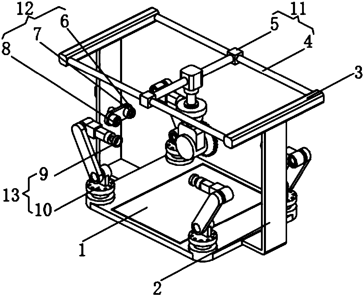
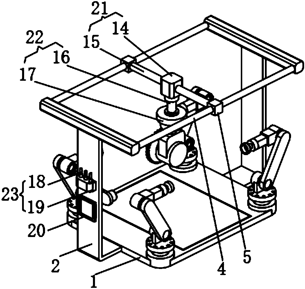
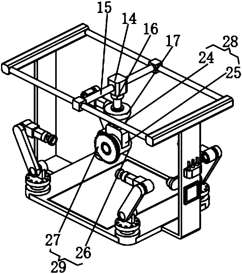
[0020] see Figure 1-3 , the present invention provides a technical solution: a flat glass fixing device capable of quickly adjusting the cutting position, including a cutting platform 1, a fixing device 13 is installed on the top of the cutting platform 1, and support frames 2 are welded on the left and right sides of the cutting platform 1 , the end of the support frame 2 is fixed with a crossbeam 3, the inner side of the crossbeam 3 is equipped with a horiz...


PUM


Abstract

The invention discloses a panel glass fixing device capable of adjusting the cutting position quickly. The device comprises a cutting platform, wherein fixing equipment is mounted on the top of the cutting platform; supporting racks are welded to the left and right sides of the cutting platform; a cross beam is fixed to the end part of each supporting rack; a transverse adjusting device is mountedon the inner side of the cross beam; a longitudinal adjusting device is mounted on the transverse adjusting device; and a height adjusting device is mounted in the bottom of the longitudinal adjusting device. The panel glass fixing device capable of adjusting the cutting position quickly positions the fixing point and the cutting position of panel glass through the positioning device, so that thepanel glass fixing device capable of adjusting the cutting position quickly is high in intelligent level and precise to position, and the work precision of the panel glass fixing device is increasedgreatly; the cutting position of the cutting device is adjusted through the transverse adjusting device, the longitudinal adjusting device, the height adjusting device and an angle adjusting device, so that the panel glass fixing device is good in flexibility and high in adjusting capacity and can meet different cutting demands.

Description

technical field [0001] The invention relates to the technical field of fixing devices, in particular to a flat glass fixing device capable of quickly adjusting the cutting position. Background technique [0002] In the prior art: the patent with authorized publication number CN 204434484U discloses a flat glass fixing device capable of quickly adjusting the cutting position, the supporting platform is fixed with a pressing device, the cutting platform is arranged above the supporting platform, and the supporting column is provided with a supporting plate , the support plate is provided with a compression bolt 1, the bottom of the compression bolt 1 is provided with a compression plate 1, a set of compression bolts is combined with a spring 1, and a compression bolt 2 is arranged in the U-shaped compression frame, and the U-shaped The compression frame is provided with a compression plate 2, and the compression bolts are combined with a spring 2. The support platform is conca...

Claims


Application Information

Patent Timeline
IPC IPC(8): C03B33/03C03B33/037
CPCC03B33/03C03B33/037
Inventor 董怡君
Owner 董怡君
Learn More