Ultra-high-temperature nitriding continuous tunnel furnace

A tunnel furnace, ultra-high temperature technology, applied in the direction of furnace, furnace type, lighting and heating equipment, etc., can solve the problems such as the air in the furnace is not easy to expel, insufficient nitriding of products, uneven atmosphere in the furnace, etc., to achieve automation Continuous operation, stable and reliable material operation, and the effect of reducing heat leakage

Active Publication Date: 2018-05-11
钢研工程设计有限公司
View PDF5 Cites 10 Cited by
  • Summary
  • Abstract
  • Description
  • Claims
  • Application Information

AI Technical Summary

Problems solved by technology

[0004] In view of the above analysis, in order to solve the above problems, the present invention proposes an ultra-high temperature nitriding continuous tunnel furnace with a unique structural layout, which overcomes the fact that the sintering temperature of the high-temperature nitriding furnace of the existing sintering equipment is generally lower than 1600°C, and the entire furnace body is not sealed well. Well, the air in the furnace is not easy to expel and clean, the atmosphere in the furnace is not uniform, and the products are not sufficiently nitrided, and continuous operation is realized.

Method used


Image

  • Ultra-high-temperature nitriding continuous tunnel furnace
  • Ultra-high-temperature nitriding continuous tunnel furnace
  • Ultra-high-temperature nitriding continuous tunnel furnace

Examples


Embodiment Construction

[0036]The present invention will be further described below with reference to the accompanying drawings, wherein the accompanying drawings constitute a part of the application and are used together with the embodiments of the present invention to explain the principles of the present invention.

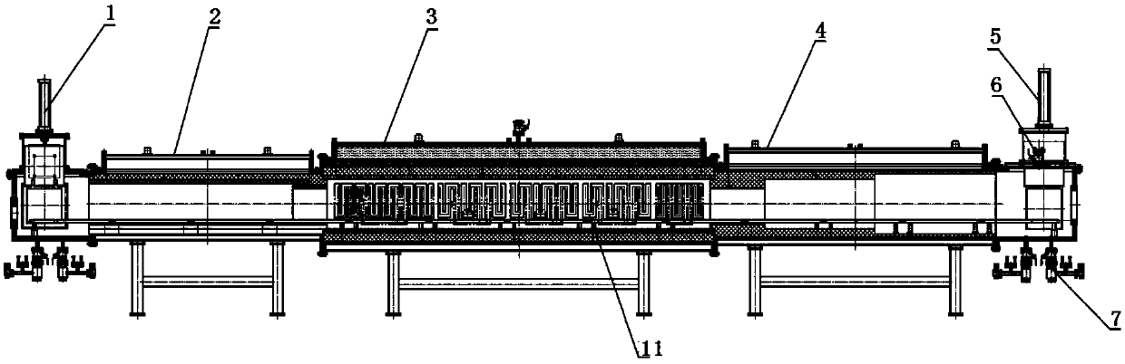
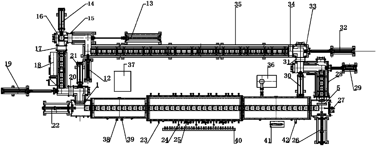
[0037] The overall plane layout of the nitriding tunnel furnace of the present invention is a closed ring structure, and the extension track platform 35 is a non-sealed structure, and the vacuum-tight gate valve 15 from the entrance of the transition cabin in the feeding area to the vacuum-tight gate valve at the exit of the transition cabin in the discharge area 34. The entire furnace body is a sealed cavity structure.

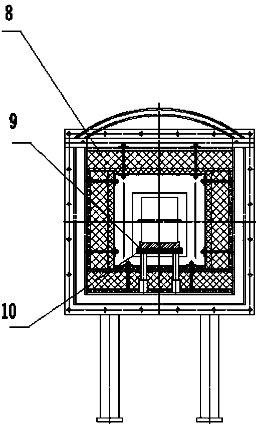
[0038] There are three zones in the furnace shell, including the preheating zone 2 in the front of the furnace body, the main heating zone 3 in the middle and the cooling zone 4 in the rear. Sliding push plate 9 loads the material into the preheating zone 2 in turn, ...


PUM


Abstract

The invention discloses an ultra-high-temperature nitriding continuous tunnel furnace. The furnace comprises an aerobic charging area, a feeding area, a furnace body and a discharging area, wherein the areas are connected in sequence to form a rectangular loop structure, and the areas are independent from one another; the feeding area, the furnace body and the discharging area are of a sealed cavity structure, and the aerobic charging area is of a non-sealing structure; and rails are laid in all the areas, and the materials enter and exit from the areas in a one-way mode. The sintering temperature of the ultra-high-temperature nitriding continuous tunnel furnace can reach 2000 DEG C, and the unique annular structure layout realizes the full-automatic closed circulation of the materials ascompactly as possible, rapid cooling and independent feeding and discharging of the materials in the furnace can be realized, the size is small, and the atmosphere in the furnace is uniform; the circulating production process of discharging the material at one end and feeding the material at the other end can be realized, and the nitriding process of the batch materials is realized; hydraulic propelling is adopted, the whole process is controlled by computers, manual intervention is not needed, and automatic continuous operation is realized; and the furnace is stable and reliable in material running, high in safety performance and low in labor intensity.

Description

technical field [0001] The invention relates to the technical field of firing equipment, in particular to an ultra-high temperature nitriding continuous tunnel furnace. Background technique [0002] Some rare earth materials, silicon nitride products, other carbon-containing products, carbides, and nitride materials need to be sintered at a high temperature of 1600-2000 ° C in a vacuum or an oxygen-free protective atmosphere. The existing high-temperature nitriding furnace that can reach a sintering temperature of 2000°C is only a batch-type sintering furnace. During the sintering process, the furnace temperature needs to be raised from room temperature to the required temperature. Take out the product. It consumes a lot of electricity and time from heating up to taking out the product. However, the existing continuous tunnel furnaces currently on the market use silicon-molybdenum rods as heating elements, and the sintering temperature is generally lower than 1600°C, which...

Claims


Application Information

Patent Timeline
Patent Type & Authority Applications(China)
IPC IPC(8): F27B9/04F27B9/30F27B9/40
CPCF27B9/042F27B9/047F27B9/30F27B9/40
Inventor 张峰朱世安程桂玲贺智勇敖雯青
Owner 钢研工程设计有限公司
Why Eureka
Try Eureka