Thin-film mute micro-switch

A micro switch and film-type technology, which is applied in the direction of electric switches, electrical components, circuits, etc., can solve the problems of being unable to apply to a quiet environment, making loud noises, and poor hand feeling, and achieves good hand feeling, long service life, and excellent structure. well-designed effects

Pending Publication Date: 2018-05-11
DONGGUAN CITY KAIHUA ELECTRONICS
View PDF0 Cites 0 Cited by
  • Summary
  • Abstract
  • Description
  • Claims
  • Application Information

AI Technical Summary

Problems solved by technology

With this conduction method, because the micro switch is often applied with a large pressing force, the corresponding action reed has a large elastic recovery force. During the two processes of its up and down bouncing, due to the relatively large force, It will generate a large force on the base and the cover, and will naturally make a loud sound, resulting in a loud sound during the process of pressing up and down, which is not suitable for a quieter environment
[0005] However, in the existing membrane switch, when the keycap is pressed down, the corresponding push rod needs to be used as a conduction pusher to knock down the conduction pusher to achieve the purpose of conduction. Usually, the conduction pusher is made of a hard material. In the process of pressing up and down, not only the hand feel is poor, but also when it is continuously pressing down the film conduction structure, it will make a loud noise, which is not suitable for a quieter environment.
[0006] It can be seen that the existing micro switches and membrane switches have problems of poor hand feeling, large cross talk and short service life in the process of pressing up and down to conduct.

Method used


Image

  • Thin-film mute micro-switch
  • Thin-film mute micro-switch
  • Thin-film mute micro-switch

Examples


Embodiment Construction

[0032] In order to further illustrate the technical means and functions adopted by the present invention to achieve the intended purpose, the specific implementation modes of the present invention will be described in detail below in conjunction with the accompanying drawings and preferred embodiments.

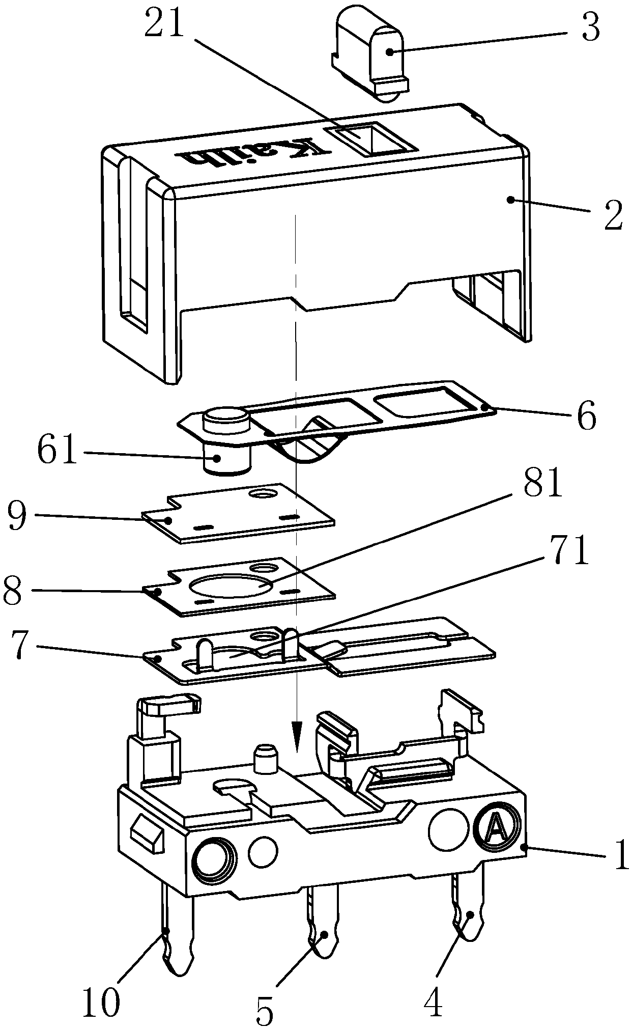
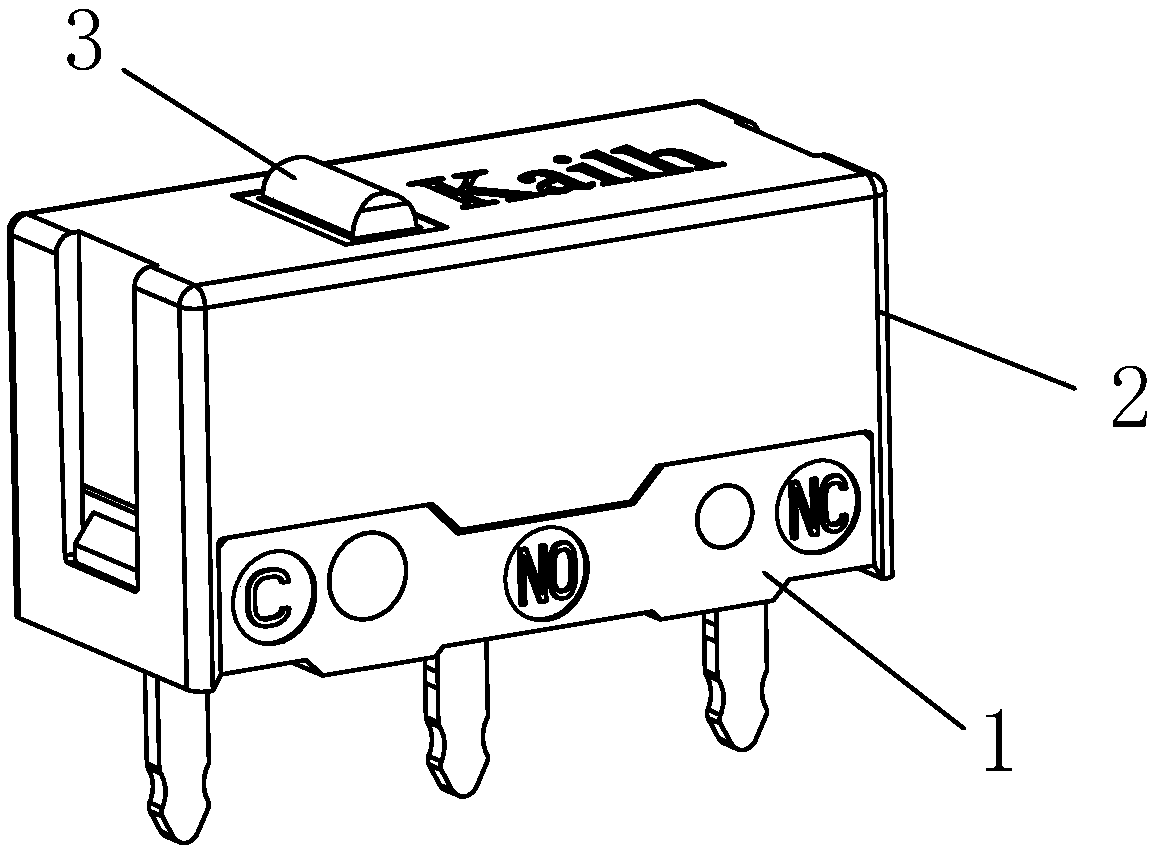
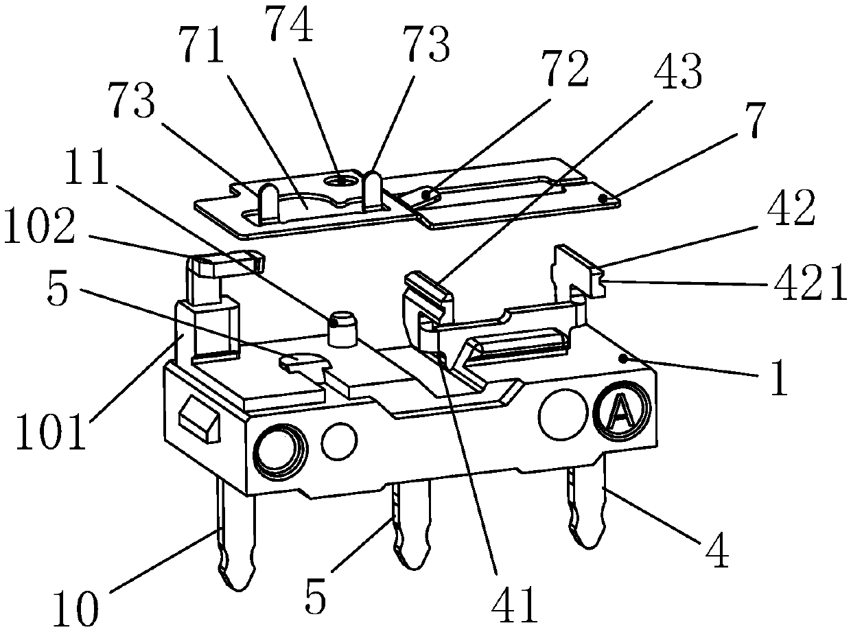
[0033] Please refer to Figure 1 to Figure 6 , the embodiment of the present invention provides a film-type silent micro switch, including a base 1 and a cover 2 covering the base 1, the cover 2 is closed on the base 1 to form an accommodating cavity, A guide core 3 is provided in the accommodating cavity, an upper opening 21 is opened on the cover 2 for the upper end of the guide core 3 to pass through, and a first terminal 4 and a second terminal 5 are provided on the base 1 . The micro switch of this embodiment also includes an elastic body 6 arranged in the accommodating cavity and below the guide core 3, a connecting piece A7 arranged on the base 1 and in contact with th...


PUM


Abstract

The invention discloses a thin-film mute micro-switch, which comprises a base, a cover, an elastic body, a connection sheet A, a gasket and a connection sheet B, wherein the cover covers the base to form an accommodating cavity; a guide core is arranged in the accommodating cavity; the base is provided with a first terminal and a second terminal; the elastic body is arranged in the accommodating cavity and located at the lower part of the guide core; the connection sheet A is arranged on the base and is in contact with the first terminal; the gasket is arranged on the connection sheet A; the connection sheet B is arranged on the gasket; a push part located at the upper part of the connection sheet B is convexly arranged at one end of the elastic body downwards; the connection sheet B is provided with a conductive layer; an upper through hole is formed in the gasket and below the conductive layer; a lower through hole is formed in the connection sheet A and below the conductive layer; the lower through hole is smaller than the upper through hole; and the upper end part of the second terminal extends into the lower through hole. The micro-switch disclosed by the invention is reasonable and novel in structural design and accurate in action in conduction and disconnection processes, has good hand feel, has a mute function and is long in service life, and the mute effect is achieved.

Description

technical field [0001] The invention relates to a micro switch, in particular to a film type silent micro switch. Background technique [0002] Micro switch is a commonly used switch mechanism. It is a contact mechanism with a small contact interval and a quick action mechanism that performs switching actions with a specified stroke and a specified force. It is widely used in industry, electronics, machinery, and governance. Gold, electricity and other fields. [0003] The working principle of the existing micro switch is: the external mechanical force acts on the action reed through the transmission element (press pin, button, lever, roller, etc.), and when the action reed moves to the critical point, an instantaneous action is generated to make the action The moving contact at the end of the reed is quickly connected or disconnected from the static contact. [0004] The existing micro switch usually adopts the method of setting the movable contact on the action reed. Bef...

Claims


Application Information

Patent Timeline
Patent Type & Authority Applications(China)
IPC IPC(8): H01H13/36
CPCH01H13/36
Inventor 吴福喜张林
Owner DONGGUAN CITY KAIHUA ELECTRONICS
Why Eureka
Try Eureka