
Grinding device for curved iron plate

A technology for iron plates and curved surfaces, applied in the field of grinding devices for curved iron plates, can solve problems such as low grinding and grinding efficiency, and achieve the effects of preventing iron filings from splashing, grinding comprehensively and fully, and reducing volume

Inactive Publication Date: 2018-05-15
重庆市合川区云天机械制造有限公司
View PDF0 Cites 1 Cited by
  • Summary
  • Abstract
  • Description
  • Claims
  • Application Information

AI Technical Summary

Problems solved by technology

However, the existing grinding devices are all for grinding flat plates, and for plate parts with a curved surface, the surface of the plate parts has a certain degree of curvature, and the existing grinding devices cannot polish the curved plate parts. Manual grinding is often required, and the grinding efficiency is low

Method used


Image

  • Grinding device for curved iron plate
  • Grinding device for curved iron plate
  • Grinding device for curved iron plate

Examples


Embodiment Construction

[0015] Further detailed explanation through specific implementation mode below:

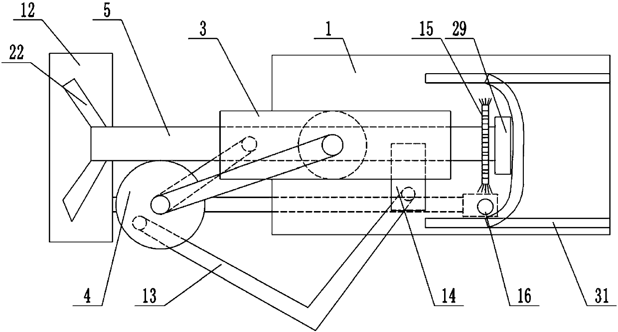
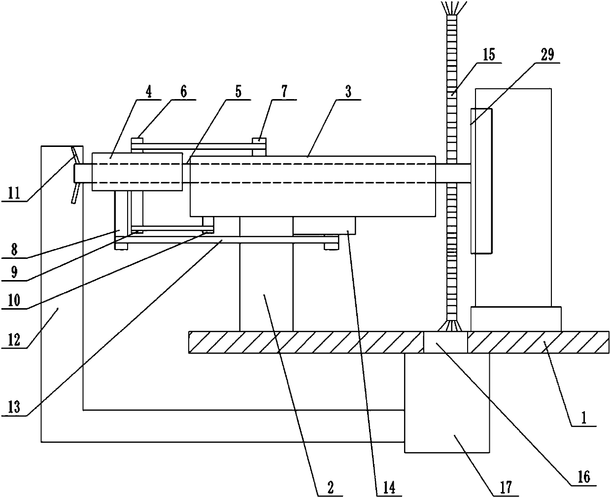
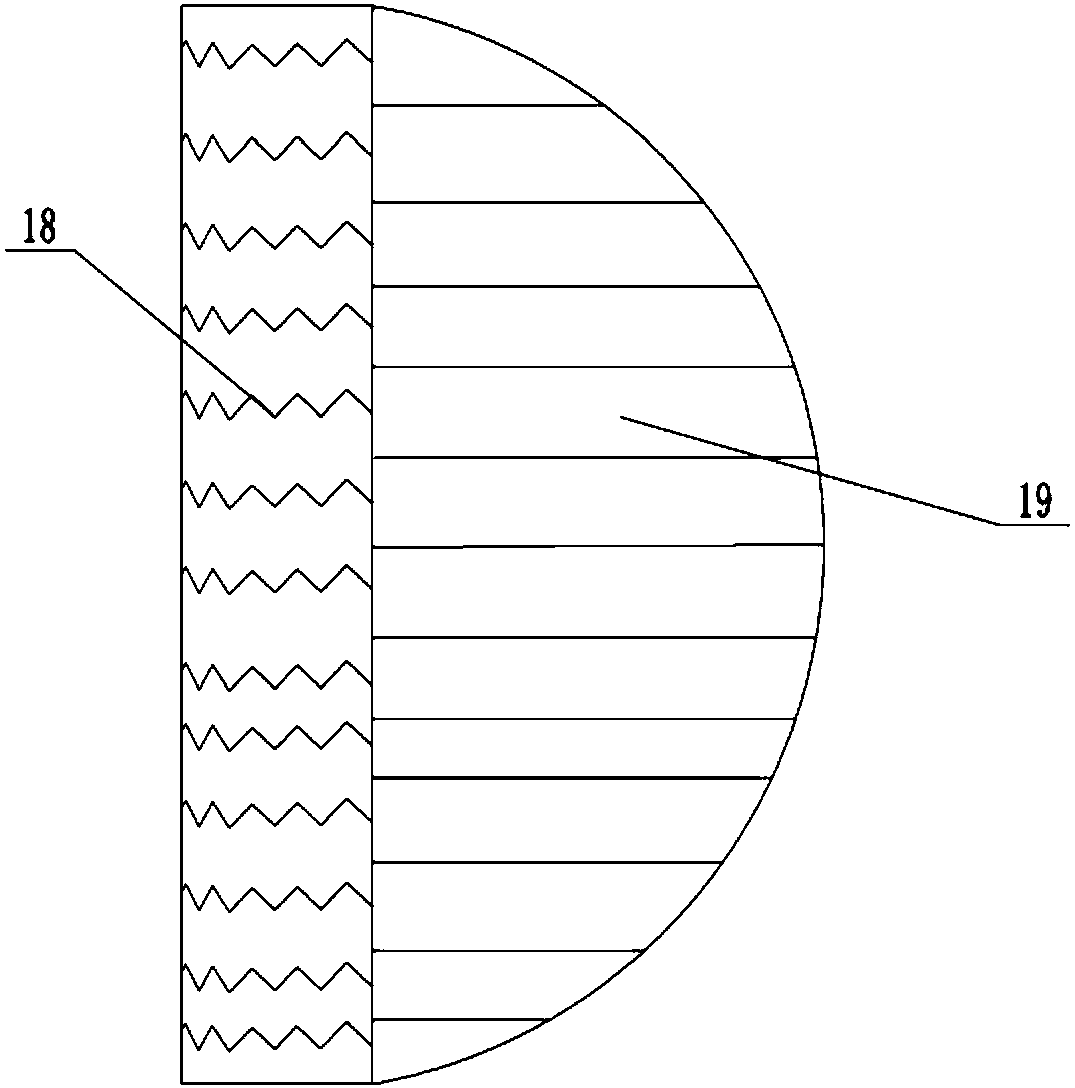
[0016] The reference signs in the drawings of the description include: base plate 1, support column 2, rotating shell 3, worm gear 4, worm screw 5, first vertical rod 6, second vertical rod 7, third vertical rod 8, rotating shaft 9, output shaft 10. Blade 11, sealing cover 12, second connecting rod 13, fixed plate 14, cleaning disc 15, iron chip hole 16, collection box 17, spring 18, grinding block 19, grinding head 29, guide rail 31.

[0017] The embodiment is basically as attached Figure 1-Figure 3 Shown: a grinding device for a curved iron plate, including a grinding head 29, a base and a rotating shell 3, a supporting column 2 is welded on the base, and the rotating shell 3 is connected to the top of the supporting column 2 through a pin shaft, and the rotating shell 3 Rotationally connected with a worm 5, both ends of the worm 5 extend to the outside of the rotating shell 3, the grinding h...


PUM


Abstract

The invention relates to a grinding device for a curved iron plate. The grinding device comprises a grinding head, a base and a rotating shell, wherein a supporting column is connected to the base, the rotating shell is rotationally connected to the supporting column, and a worm is arranged in the rotating shell in a rotating mode; the two ends of the worm extend to the outer side of the rotatingshell; the grinding head is connected to one end of the worm, and the other end of the worm is meshed with a worm gear; a first connecting rod is connected between the worm gear and the rotating shell, a motor and a fixed plate are arranged at the bottom of the rotary shell, and a second connecting rod is connected between the bottom surface of the worm gear and the fixed plate; the bottom of theworm gear is connected with a rotating shaft, a belt is connected between an output shaft of the motor and the rotating shaft, and a scrap iron hole is formed in the base; a collecting box is arrangedbelow the base, and the collecting box communicates with the scrap iron hole; and the end, far away from the grinding head, of the worm is fixedly connected with blades, and the end, far away from the grinding head, of the worm is covered with a sealing cover communicating with the collecting box; and the grinding head comprises a baffle and a plurality of grinding blocks, and a spring is connected between the grinding blocks and the baffle. According to the grinding device for a curved iron plate, grinding of the curved iron plate is realized.

Description

technical field [0001] The invention relates to the field of grinding motorcycle parts, in particular to a grinding device for curved iron plates. Background technique [0002] There are many kinds of accessories for motorcycles, and the shapes of motorcycle accessories are different. Motorcycle accessories mainly include various types of covers, baffles, bolts, handlebars, gears and flywheels. Among them, plate parts such as cover plates and baffles are mostly made of iron plates. In order to improve the smoothness of plate parts such as cover plates and baffles and remove burrs on the surface of plate parts, in the processing of plate parts, often Grinding plate parts. However, the existing grinding devices are all for grinding flat plates, and for plate parts with a curved surface, the surface of the plate parts has a certain degree of curvature, and the existing grinding devices cannot polish the curved plate parts. Manual grinding is often required, and the grinding e...

Claims


Application Information

Patent Timeline
IPC IPC(8): B24B19/26B24B47/12B24B47/20B24B55/06
CPCB24B19/26B24B47/12B24B47/20B24B55/06
Inventor 张科
Owner 重庆市合川区云天机械制造有限公司
Learn More