
Environment-friendly mechanical machining waste collection device

A technology for mechanical processing and waste collection, applied in metal processing equipment, metal processing machinery parts, manufacturing tools, etc., can solve the problems of unfavorable collection and cleaning, unfavorable use of machine tools, etc., and achieve the effect of preventing iron filings from splashing

Active Publication Date: 2019-07-02
SHAANXI SCI TECH UNIV
View PDF7 Cites 2 Cited by
  • Summary
  • Abstract
  • Description
  • Claims
  • Application Information

AI Technical Summary

Problems solved by technology

[0002] For example, the publication number CN204894072U, the name is a waste collection device, including a support frame, support plates are provided on both sides above the support frame, and a recovery tank is provided below between the support plates. Longer than the circumference of its lower port, a flat plate is provided on the upper surface of the support frame, a collection box is provided at the lower end of the support frame, a hose and a moving plate are arranged in the collection box, the cylinder is fixed on the flat plate, and the piston of the cylinder The rod passes through the flat plate and is connected with the moving plate. One side of the collection box is provided with a hole connected to the pipeline, and the other end of the pipeline is connected with the fan. Both sides of the collection box are provided with chute. The vertical beams on both sides of the machine are equipped with slide rails that match the chute; however, in machining, it is often difficult to collect and clean because iron splashes fall in the gaps of the machine tool, or the iron filings caused by collecting and processing iron filings Splash falling in the gap of the machine tool is not conducive to collection and cleaning and is not conducive to the use of the machine tool

Method used


Image

  • Environment-friendly mechanical machining waste collection device
  • Environment-friendly mechanical machining waste collection device
  • Environment-friendly mechanical machining waste collection device

Examples


specific Embodiment approach 1

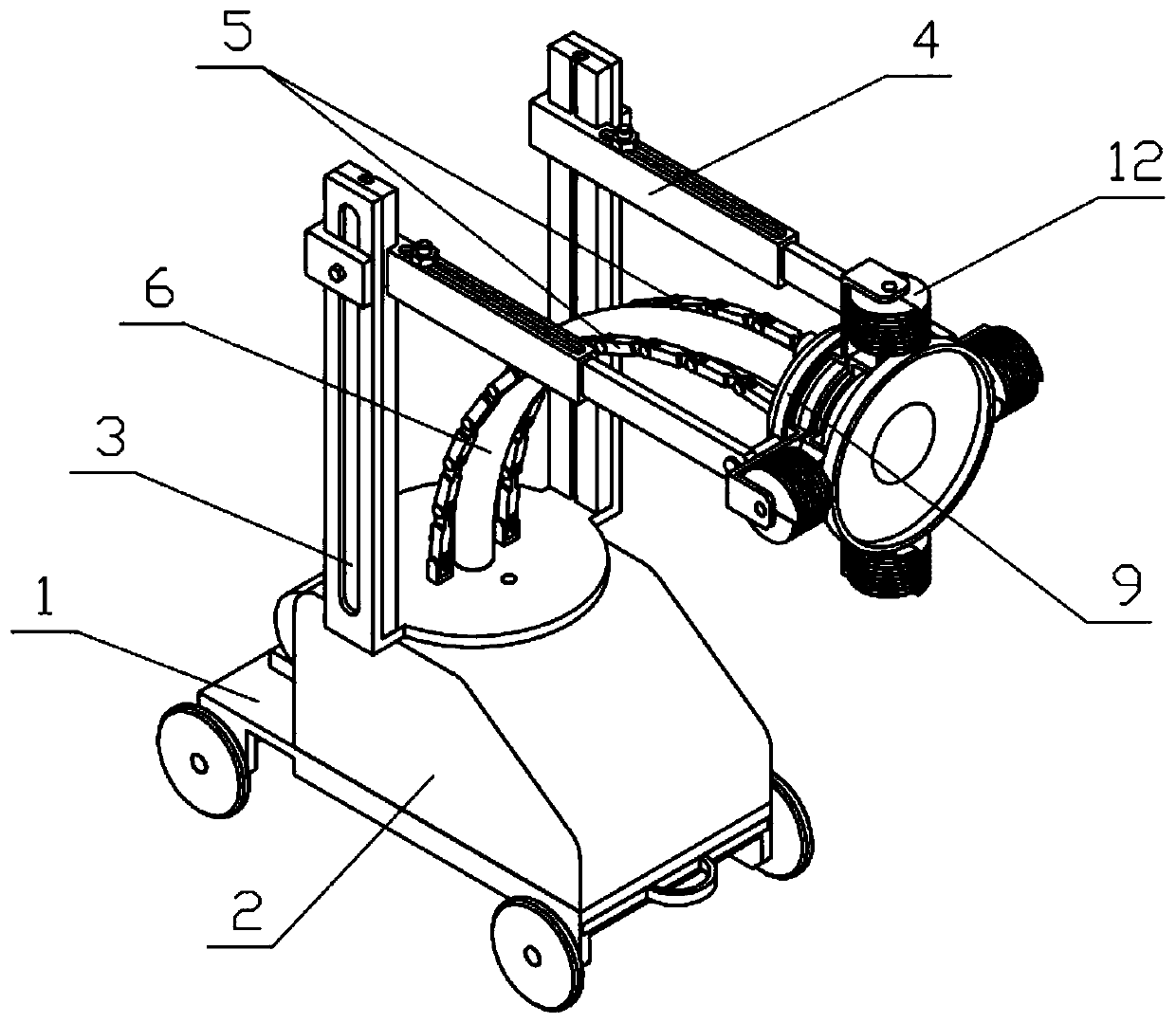
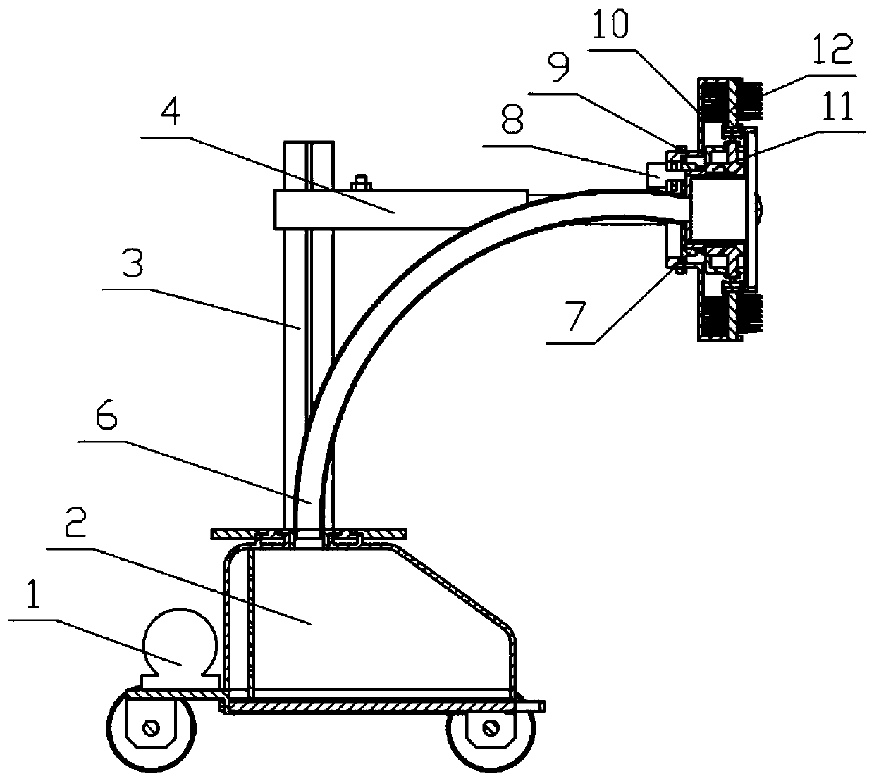
[0047] Combine below Figure 1-22 Describe this embodiment, an environment-friendly mechanical processing waste collection device, including a moving chassis 1, a collection box 2, a lifting support 3, a sliding support 4, a support mechanism 5, a collection pipe 6, a collection support 7, a rotating mechanism 8, a limit The rotating ring 9, the rotating bracket I10, the rotating bracket II11 and the collection mechanism 12, the collection box 2 is fixedly connected to the moving chassis 1, the moving chassis 1 is provided with a suction pump 1-2, the output end of the suction pump 1-2 and The collection box 2 is connected, and the lifting bracket 3 is rotatably connected to the collection box 2. There are two sliding brackets 4, and the two sliding brackets 4 are slidingly connected to the lifting bracket 3. There are two supporting mechanisms 5, and the two supporting mechanisms The two ends of 5 are respectively hinged on the lifting bracket 3 and the collection bracket 7, ...

specific Embodiment approach 2

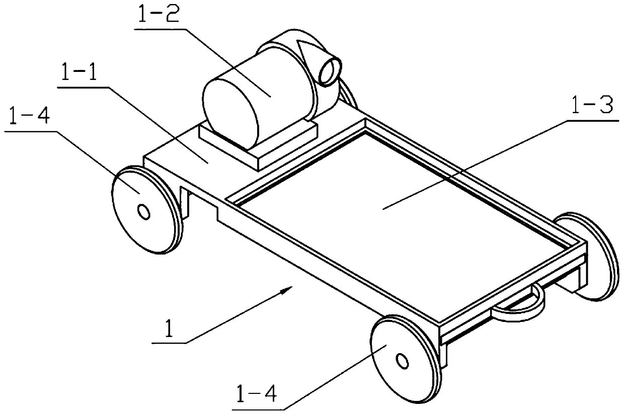
[0049] Combine below Figure 1-22 Describe this embodiment, this embodiment will further explain Embodiment 1, the said sports chassis 1 also includes a chassis body 1-1, a closing plate 1-3, a moving wheel 1-4 and a closing screw 1-5, the chassis body 1- 1 is slidably connected with a closing plate 1-3, the four corners of the chassis body 1-1 are rotatably connected with a motion wheel 1-4, two closing screws 1-5 are provided, and the two closing screws 1-5 are all worn The chassis body 1-1 is screwed to the closing plate 1-3.

specific Embodiment approach 3

[0051] Combine below Figure 1-22 Illustrate this embodiment, and this embodiment will further illustrate Embodiment 2. The collection box 2 includes a collection box 2-1, a rotating support platform 2-2, a rotating groove 2-3 and a screening plate 2-4, and collects The box body 2-1 is fixedly connected on the chassis body 1-1, and the collection box body 2-1 is fixedly connected with a rotating supporting platform 2-2, and the rotating supporting platform 2-2 is provided with a rotating groove 2-3, and the collecting box body 2-1 is fixedly connected with a screening plate 2-4, the output end of the suction pump 1-2 communicates with the collection box 2-1, and the screening plate 2-4 is located at the output end of the suction pump 1-2 and the rotating support platform Between 2-2, the rotating groove 2-3 and the rotating support table 2-2 are coaxially arranged; when in use, the suction pump 1-2 is started, so that the output end of the suction pump 1-2 generates suction, a...


PUM


Abstract

The invention relates to a collection device, in particular to an environment-friendly mechanical machining waste collection device. The environment-friendly mechanical machining waste collection device comprises a moving chassis, a collection box, a lifting support, a sliding support, supporting mechanisms, a collection pipeline, a collection support, a rotating mechanism, a limiting rotation ring, a rotating support I, a rotating support II and collecting mechanisms. The suction generated by a suction pump arranged on the moving chassis enables the collection pipeline to generate suction toabsorb and collect iron chips in the machining process, and the suction collects the machined iron chips in gaps of a machine tool into the collection box. Through the lifting support, the sliding support and the support mechanism, a certain supporting role is played to the collection pipeline, the collection support, the rotating mechanism, the limiting rotation ring, the rotating support I, therotating support II and the collection mechanisms, the different positions of the collection mechanisms in a space are changed to facilitate the use, the collection mechanisms remove the iron chips from the gaps of the machine tool during rotation while the collection mechanisms collect the iron chips to the centers of the four collection mechanisms to prevent splashing.

Description

technical field [0001] The invention relates to a collecting device, in particular to an environment-friendly mechanical processing waste collecting device. Background technique [0002] For example, the publication number CN204894072U, the name is a waste collection device, including a support frame, support plates are provided on both sides above the support frame, and a recovery tank is provided below between the support plates. Longer than the circumference of its lower port, a flat plate is provided on the upper surface of the support frame, a collection box is provided at the lower end of the support frame, a hose and a moving plate are arranged in the collection box, the cylinder is fixed on the flat plate, and the piston of the cylinder The rod passes through the flat plate and is connected with the moving plate. One side of the collection box is provided with a hole connected to the pipeline, and the other end of the pipeline is connected with the fan. Both sides of...

Claims


Application Information

Patent Timeline
IPC IPC(8): B23Q11/00
CPCB23Q11/0046
Inventor 赵佐平邵先钊季晓晖刘智峰宋凤敏汤波岳思羽李琛刘瑾
Owner SHAANXI SCI TECH UNIV
Learn More