
Image pickup lens

A lens and lens technology, applied in the field of imaging lenses, can solve the problems of miniaturization, large size and long length of unfavorable application equipment, and achieve the effect of reducing the total optical length, improving the imaging quality, and satisfying the wide-angle field of view.

Active Publication Date: 2018-05-15
湖南莱通光学科技有限公司
View PDF2 Cites 13 Cited by
  • Summary
  • Abstract
  • Description
  • Claims
  • Application Information

AI Technical Summary

Problems solved by technology

[0002] In recent years, with the advancement of the technology industry, imaging systems have been developing towards multi-functions, such as mobile phone image communication, smart home monitoring systems, and automotive imaging systems. However, traditional imaging lenses are long in length and large in size. , which is not conducive to the miniaturization of application equipment. In order to save space, most imaging lenses adopt a three-piece lens design, but most of the existing three-piece lenses have a field of view angle below 80 degrees, and the first piece is mostly a positive power lens. design
Due to the application requirements of the imaging system, the field of view angle needs to reach more than 80 degrees or even reach 160 degrees. However, the existing three-piece lens design is difficult to meet the requirements of wide angle, large aperture and short system length. Therefore, it also has certain limitations. room for improvement

Method used


Image

  • Image pickup lens
  • Image pickup lens
  • Image pickup lens

Examples


Embodiment 1

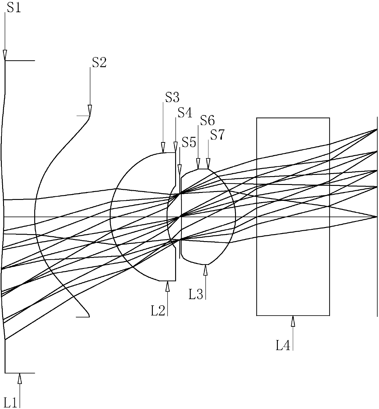
[0086] Each lens of the imaging lens is further set according to the specific data of each parameter in the above formula. The data is shown in Table 1, wherein f=0.79, Fno=2.4, FOV=100 degrees, and Fno represents the number of apertures.

[0087] Table 1. Data sheet of each lens in the lens assembly

[0088]

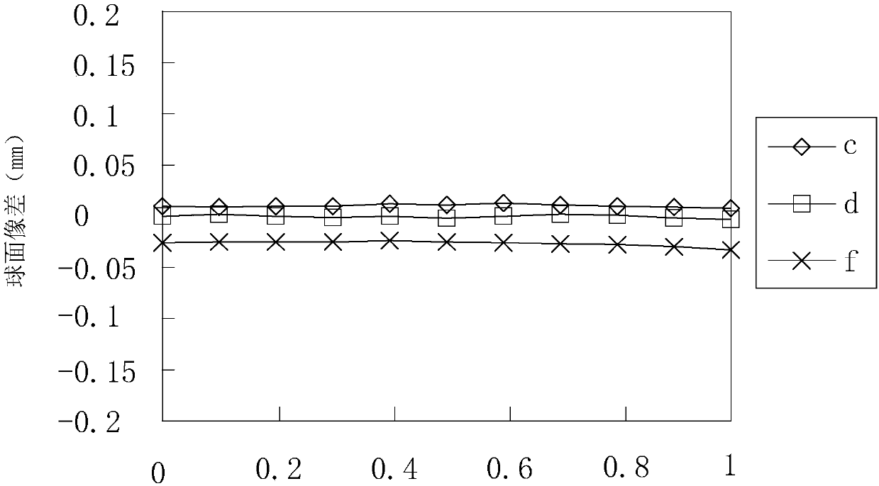
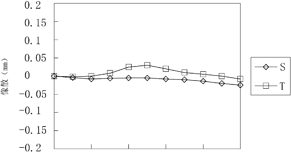
[0089] The above data is simulated by ZEMAX software to analyze the imaging capability of the lens, such as Figure 2 to Figure 4 shown.

Embodiment 2

[0091] Each lens of the imaging lens is further set according to the specific data of each parameter in the above formula. The data is shown in Table 2, where f=1.02, Fno=2.8, FOV=120 degrees, and Fno represents the number of apertures.

[0092] Table 2. Data sheet of each lens in the lens assembly

[0093]

[0094] The above data is simulated by ZEMAX software to analyze whether the imaging of the lens meets the requirements, such as Figure 6 to Figure 12 shown.

Embodiment 3

[0096] Each lens of the imaging lens is further set according to the specific data of each parameter in the above formula, and the data is shown in the following table for example.

[0097]

[0098] The above data is simulated by ZEMAX software to analyze the imaging capability of the lens, such as Figure 13 to Figure 18 shown.

[0099] Through the above-mentioned simple three-piece lens design, the accuracy of the imaging lens is better, the definition is better, the color reproduction is more accurate, the light reflection in the lens is reduced, and the lens size is reduced accordingly, meeting the wide-angle field of view. And the aspherical lens has the characteristics of large aperture, which can adapt to places with low light, so the application field is wider.


PUM


Abstract

The invention discloses an image pickup lens. With the image pickup lens adopted, the problem that the field-of-view angle of a three-piece lens in the prior art is relatively small can be solved. According to the technical schemes of the invention, the image pickup lens includes three sets of lenses which are arranged sequentially along an optical axis from an object side to an image side. The first lens is a negative-optical power lens, and the image-side surface of the first lens is a concave surface. The second lens is a positive-optical power lens, and the object-side surface of the second lens is a convex surface. The third lens is a positive-optical power lens, and the image-side surface of the third lens is a convex surface. The lenses satisfy a relationship that -0.9<f1 / f<-0.5, wherein f1 is the focal length of the first lens, and f is the effective focal length of the entire image pickup lens. According to image pickup lens of the present invention, a simplified three-piece lens design is adopted; the optical power, concave surfaces and convex surfaces of the lenses are combined, and therefore, the total optical length of the image pickup lens can be effectively reduced,and a requirement for a wide field-of-view angle can be satisfied, and imaging quality can be improved.

Description

technical field [0001] The invention relates to an optical system composed of lenses, in particular to an imaging lens. Background technique [0002] In recent years, with the advancement of the technology industry, imaging systems have been developing towards multi-functions, such as mobile phone image communication, smart home monitoring systems, and automotive imaging systems. However, traditional imaging lenses are long in length and large in size. , which is not conducive to the miniaturization of application equipment. In order to save space, most imaging lenses adopt a three-piece lens design, but most of the existing three-piece lenses have a field of view angle below 80 degrees, and the first piece is mostly a positive power lens. design. Due to the application requirements of the imaging system, the field of view angle needs to reach more than 80 degrees or even reach 160 degrees. However, the existing three-piece lens design is difficult to meet the requirements ...

Claims


Application Information

Patent Timeline
IPC IPC(8): G02B13/00
CPCG02B13/0035
Inventor 刘江峰卢友文
Owner 湖南莱通光学科技有限公司
Learn More