Head support device for neurological surgery patients

A support device and neurosurgery technology, applied in the field of neurosurgery medical equipment, can solve problems such as head trauma, single degree of freedom of head support, head shaking, etc.

Inactive Publication Date: 2018-05-18
朱兵
View PDF3 Cites 12 Cited by
  • Summary
  • Abstract
  • Description
  • Claims
  • Application Information

AI Technical Summary

Problems solved by technology

[0002] Since there are a large number of nerves or spinal cords in the human brain, many patients with nerve-related diseases need to be operated on the head. During the operation, the patient's head must not shake a little, so most A head brace is needed, but most of the head braces currently used clinically are fixed on the skull by inserting scalp needles into the patient's scalp. This method obviously causes trauma to the head, and most of the head braces used now are It is a single degree of freedom or the adaptability is too poor. When the fixed position needs to be replaced, it is easy to cause the head to shake, which is not good for the operation.

Method used


Image

  • Head support device for neurological surgery patients
  • Head support device for neurological surgery patients
  • Head support device for neurological surgery patients

Examples


Embodiment Construction

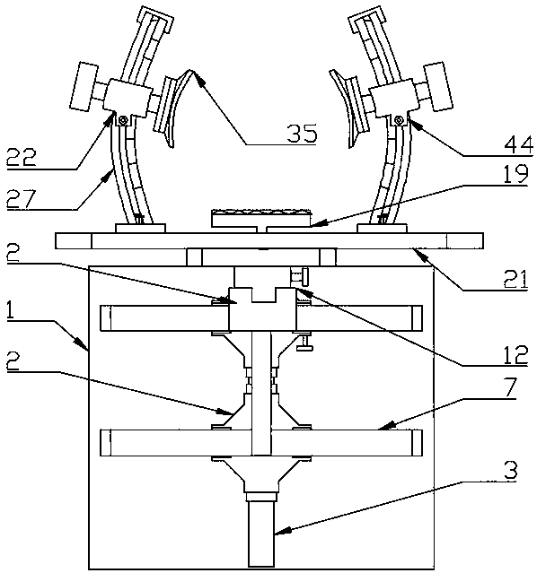
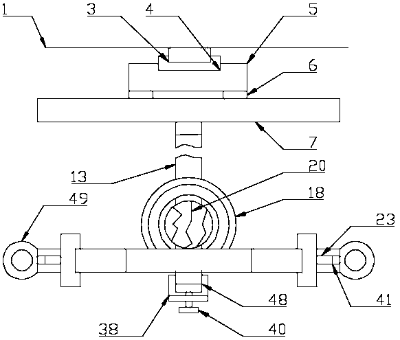
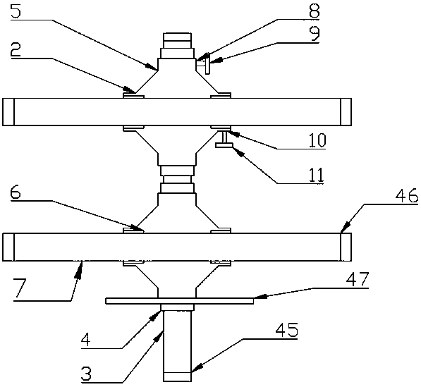
[0022] The present invention is specifically described below in conjunction with accompanying drawing, as Figure 1-6 As shown, a head support device for neurosurgical patients includes an operating table installation surface 1, and a cross moving device 2 is arranged in front of the operating table installation surface 1, and the cross moving device 2 is located on the operating table installation surface. 1 The vertical slide rail 3 fixedly connected to the middle position of the operating table installation surface 1 at the front, two vertical slide blocks located in front of the vertical slide rail 3 and distributed up and down and slidingly connected to the front surface of the vertical slide rail 3 4, located on the vertical slide block 4 The cross connector 5 fixedly connected to the two vertical sliders 4 at the front, the horizontal slider 6 located on the front surface of the cross connector 5 and distributed left and right and fixedly connected to the cross connector...


PUM


Abstract

The invention discloses a head support device for neurological surgery patients. The head support device comprises an operating table mounting surface. A cross movement device is arranged at the frontof the operating table mounting surface, a support device is arranged at the front of the cross movement device, a left fixing device is arranged on the left side of a position above the support device and comprises a mounting slide groove, a left slider, a left curved bar, a left slide groove, a left rotary slider, left threaded holes, a left ejector rod and a left turntable, the mounting slidegroove is formed in the middle of the upper surface of a mounting rod, the left slider is positioned in the mounting slide groove and is slidably connected with the mounting rod, the left curved bar is positioned on the upper side of the left slider and is fixedly connected with the upper surface of the left slider, the left slide groove is formed in the middle of the front surface of the left curved bar, the left rotary slider is positioned in the left slide groove and is slidably connected with the left curved bar, the left threaded holes are formed in the middles of the left side surface and the right side surface of the left rotary slider, the left ejector rod is nested in the left threaded holes and is rotationally connected with the left rotary slider, and the left turntable is positioned on the right side of the left ejector rod and is fixedly connected with the right surface of the left ejector rod. The head support device has the advantages of simple structure and high practicality.

Description

technical field [0001] The invention relates to the technical field of neurosurgery medical instruments, in particular to a head support device for neurosurgery patients. Background technique [0002] Since there are a large number of nerves or spinal cords in the human brain, many patients with nerve-related diseases need to be operated on the head. During the operation, the patient's head must not shake a little, so most A head brace is needed, but most of the clinically used head braces are inserted into the patient's scalp with scalp needles and fixed on the skull. This method obviously causes trauma to the head, and most of the head braces used now are It is a single degree of freedom or the adaptability is too poor. When the fixed position needs to be changed, it is easy to cause the head to shake, which is not good for the operation. Contents of the invention [0003] The purpose of the present invention is to solve the above problems, and to design a head support ...

Claims


Application Information

Patent Timeline
Patent Type & Authority Applications(China)
IPC IPC(8): A61G13/12A61B90/14
CPCA61B90/14A61G13/121A61G2203/70
Inventor 赵国峰
Owner 朱兵
Why Eureka
Try Eureka