Card pushing mechanism applied to printer, and printer

A technology of printer and card feeding, applied in the directions of printing device, printing, object supply, etc., can solve the problem of card receiving failure, and achieve the effect of improving the probability of successful push

Pending Publication Date: 2018-05-18
XIAMEN HANIN ELECTRONICS TECH CO LTD
View PDF8 Cites 0 Cited by
  • Summary
  • Abstract
  • Description
  • Claims
  • Application Information

AI Technical Summary

Problems solved by technology

[0003] The invention provides a device aimed at improving the problem that the small angle between the print head sheet and the printing rubber roller in the micro-printer easily leads to card receiving failure

Method used


Image

  • Card pushing mechanism applied to printer, and printer
  • Card pushing mechanism applied to printer, and printer
  • Card pushing mechanism applied to printer, and printer

Examples


Embodiment 1

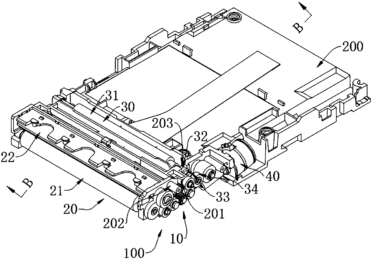
[0034] refer to Figure 1 to Figure 7 As shown, the card feeding mechanism 100 includes a card feeding device 30 , a printing device 20 , a transmission device 10 and a driving device 40 . The card feeding device 30 is located upstream of the printing device 20 and is used to push the card X to a first direction. The printing device 20 is used to receive the card X pushed by the card feeding device 30 , the printing device 20 leaves printing marks on the card X, and continues to push the card X to the first direction. The driving device 40 is connected with the transmission device 10 , and the driving device 40 drives the transmission device 10 . By arranging the card feeding device 30 upstream of the printing device 20, the problem that the card X is skewed during the transport process, and the skew cannot be pushed in place can be avoided.

[0035] The transmission device 10 is connected with the card feeding device 30 and the printing device 20 at the same time, and pushes...

Embodiment 2

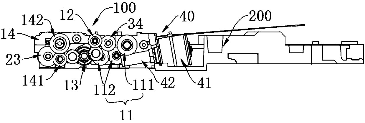
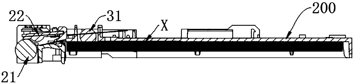
[0051] refer to Figure 1 to Figure 7 As shown, the printer includes the card feeding mechanism 100 in Embodiment 1, and further includes a base 200 on which the card feeding mechanism 100 is arranged. The first rubber roller 31 and the second rubber roller 21 are arranged in parallel on the machine base 200, and the axes of the first rubber roller 31 and the second rubber roller 21 are perpendicular to the first direction. The base 200 is provided with a first bump 201 that cooperates with the first stopper 131A, and the first stopper 131A cooperates with the first bump 201 to increase the frictional resistance between the two and improve the position limitation. stability. The base 200 is provided with a second protrusion 202 that cooperates with the second limiting portion 131B, and the second limiting portion 131B is surface-fitted with the second protrusion 202 , so that the position limiting stability is high.

[0052] In the embodiment, the end of the first rubber rol...


PUM


Abstract

The invention provides a card pushing mechanism applied to a printer. The card pushing mechanism comprises a card pushing device, a printing device, a transmission device and a driving device. The card pushing device is used for pushing cards in the first direction. The printing device is used for receiving the cards pushed by the card pushing device, leaving printing marks on the cards and continuing pushing the cards in the first direction. The transmission device comprises a switching set which comprises the card pushing state and the printing state, under the card pushing state, the transmission device drives the card pushing device and the printing device, and under the printing state, the transmission device is disengaged from the card pushing device and drives the printing device. The driving device is connected with the transmission device and used for driving the transmission device. The different states are switched through the switching set, at the card pushing stage, the card pushing device and the printing device are driven simultaneously, the two devices simultaneously work to push the cards jointly, thus the cards are stably pushed into the printing device, and the success probability of card pushing is increased.

Description

technical field [0001] The invention relates to the field of printers, in particular to a card feeding mechanism applied to a printer and the printer thereof. Background technique [0002] Card printers are widely used in ticket vending machines, card machines, cameras and other equipment. However, in some thin and miniature card printers, the print head has a small angle with respect to the printing roller, and the card needs to be accurately and properly delivered between the head sheet and the printing roller before the card can be successfully received. As a result, the success rate of receiving cards at the printing roller is greatly reduced. Therefore, how to design a card feeding mechanism with a high success rate in a miniature card printer is very important. Contents of the invention [0003] The invention provides a device aimed at improving the problem that the small included angle between the printing head sheet and the printing rubber roller in the micro-pri...

Claims


Application Information

Patent Timeline
Patent Type & Authority Applications(China)
IPC IPC(8): B65H5/06B41J13/12
CPCB65H5/06B41J13/12B65H2701/1914B65H2701/1912
Inventor 林永明汪俊荣
Owner XIAMEN HANIN ELECTRONICS TECH CO LTD
Why Eureka
Try Eureka