IU type three-dimensional code bolt self-locking padlock

A three-dimensional code bolt and self-locking technology, which is applied in the field of locks, can solve the problems of fragile lock bolt insertion mode, difficult key slot processing, and limited order of magnitude, so as to achieve firm locking mode, enhanced prying resistance, and miniaturization Effect

Inactive Publication Date: 2018-05-18
武思军
View PDF0 Cites 0 Cited by
  • Summary
  • Abstract
  • Description
  • Claims
  • Application Information

AI Technical Summary

Problems solved by technology

[0002] At present, mechanical locks are mainly pin locks and blade locks with key slots. Because the processing of key slots is difficult, the material of the lock cylinder can only use low-strength brass. The existing pin lock cylinder uses an axial lock cylinder. This requires that there must be a key slot and a key handle rod, the pins are arranged in a linear arrangement, and the key teeth are also arranged in a linear manner. The concave and convex angle of the key teeth must be less than about 45 degrees to facilitate insertion into the lock cylinder, so that the longest pin and the shortest pin The length of the difference cannot be much larger than the diameter of the pins, which greatly limits the number of pins and the number of pins, usually only single digits, and the key amount is only a few thousand
Generally, the bolt of the lock is directly inserted, so most of the burglars destructively unlock the lock by picking the bolt, which shows that the common way of inserting the bolt is very fragile.

Method used


Image

  • IU type three-dimensional code bolt self-locking padlock
  • IU type three-dimensional code bolt self-locking padlock
  • IU type three-dimensional code bolt self-locking padlock

Examples


Embodiment Construction

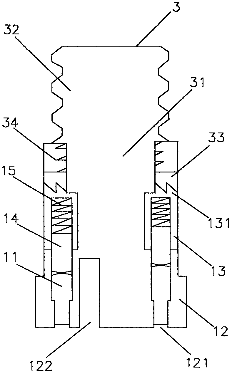
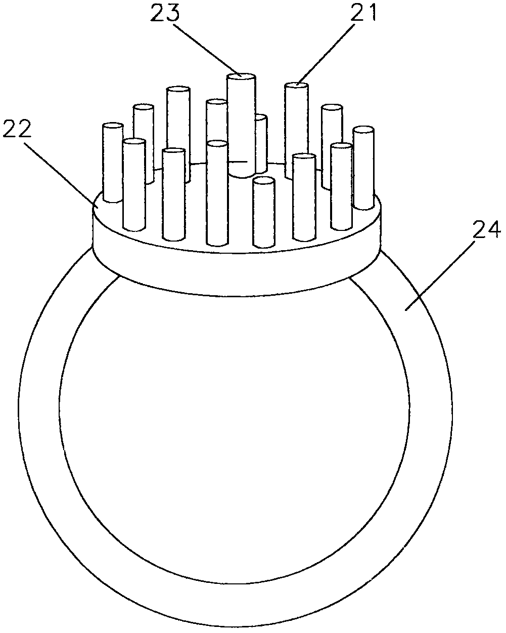
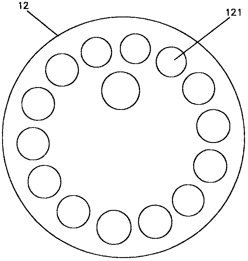
[0020] Implementation column, such as figure 1 , figure 2 , image 3 , Figure 4 , Figure 5 and Figure 6 Shown: an IU type three-dimensional code bolt self-locking padlock, which is composed of a three-dimensional code bolt self-locking lock core 1, a lock tube 4, an I-shaped locking bar 5 and a U-shaped locking bar 6, wherein the three-dimensional code bolt self-locking lock core 1 includes code lock screen 12, embolus honeycomb 13, screw shaft rod 3, helical tooth pad 33, compression spring 34, lock code 11, embolus 14 and spring 15, code lock screen 12 and embolus honeycomb 13, closely attached According to the two-dimensional arrangement, the code lock screen 12 has many holes 121 that are thin at the front and thick at the back, and the holes 121 through which the two ends are connected. There are lock codes 11 of various code numbers, forming a three-dimensional layout of lock codes 11. The lock codes 11 are in the shape of needle cylinders, thin in front and thi...


PUM


Abstract

The invention discloses an IU type three-dimensional code bolt self-locking padlock, and relates to a lock. In order to overcome the disadvantages of small key amount of existing mechanical locks, small material strength of lock cylinders and weak lock tongue way, the IU type three-dimensional code bolt self-locking padlock abandons traditional pivoted lock cylinders; and in three dimensions of the space, lock codes are fully laid out, and a key code needle bar is directly used to push a lock code needle bar to achieve high key amount and high strength of the lock cylinders. According to a lock cylinder technology, a lock code screen and an embolus honeycomb are closely adjacent to each other, a plurality of holes are formed in the lock code screen in a two-dimensional mode, and a plurality of lock codes are installed in the holes to form a three-dimensional layout of the lock codes; a plurality of nests are arranged in the embolus honeycomb in a two-dimensional mode, and embolus and springs are installed in the nests; a screw shaft rod is connected to the lock screen, and a helical tooth pad and a compression spring are arranged between the shaft rod portion and the screw portionof the screw shaft rod; and a helical tooth face is disposed at the rear end of the embolus honeycomb, a lock pipe is connected to the front end of an I-shaped lock rod, an axial hole is formed in aninner cavity of the lock pipe, and a screw hole is formed in the front end of an U-shaped lock rod and is meshed with the screw portion for locking.

Description

technical field [0001] The invention relates to a lock, in particular to a padlock with a three-dimensional layout of a lock code and a key code and a lock core inserted into a screw hole in a bolt manner. Background technique [0002] At present, mechanical locks are mainly pin locks and blade locks with key slots. Because the processing of key slots is difficult, the material of the lock cylinder can only use low-strength brass. The existing pin lock cylinder uses an axial lock cylinder. This requires that there must be a key slot and a key handle rod, the pins are arranged in a linear arrangement, and the key teeth are also arranged in a linear manner. The concave and convex angle of the key teeth must be less than about 45 degrees to facilitate insertion into the lock cylinder, so that the longest pin and the shortest pin The differential length cannot be much larger than the diameter of the marbles, which greatly limits the number of marbles and the number of marbles, u...

Claims


Application Information

Patent Timeline
IPC IPC(8): E05B67/00E05B67/06E05B19/00E05B19/08
CPCE05B67/00E05B19/00E05B19/0017E05B67/06
Inventor 武思军
Owner 武思军
Why Eureka
Try Eureka