Three-dimensional code bolt wall core lock

A three-dimensional code bolt and core lock technology, which is applied in the field of locks, can solve the problems of low key quantity, limited order of magnitude, and only single digits, and achieve the effects of reducing processing difficulty, simplifying the basic structure, and enhancing prying resistance

Inactive Publication Date: 2018-07-24
武思军
View PDF0 Cites 0 Cited by
  • Summary
  • Abstract
  • Description
  • Claims
  • Application Information

AI Technical Summary

Problems solved by technology

[0002] At present, mechanical locks are mainly pin locks and blade locks with key slots. Because the processing of key slots is difficult, the material of the lock cylinder can only use low-strength brass. The existing pin lock cylinder uses an axial lock cylinder. This requires that there must be a key slot and a key handle rod, the pins are arranged in a linear arrangement, and the key teeth are also arranged in a linear manner. The concave and convex angle of the key teeth must be less than about 45 degrees to facilitate insertion into the lock cylinder, so that the longest pin and the shortest pin The length of the difference cannot be much larger than the diameter of the pins, which greatly limits the number of pins and the number of pins, usually only single digits, and the key amount is only a few thousand
Generally, the locking points of door locks are set on the side of the door frame, and the deadbolt is inserted. Therefore, most thieves destructively unlock the room by prying open the locking points of the door. This shows that the current common locking point method is very fragile.

Method used


Image

  • Three-dimensional code bolt wall core lock
  • Three-dimensional code bolt wall core lock
  • Three-dimensional code bolt wall core lock

Examples


Embodiment Construction

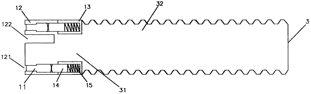
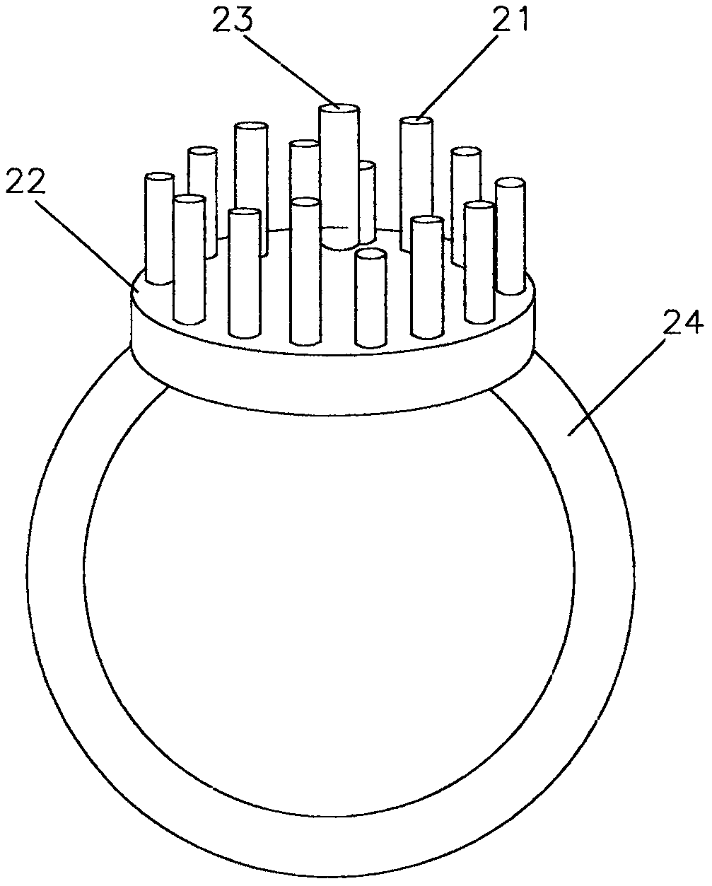
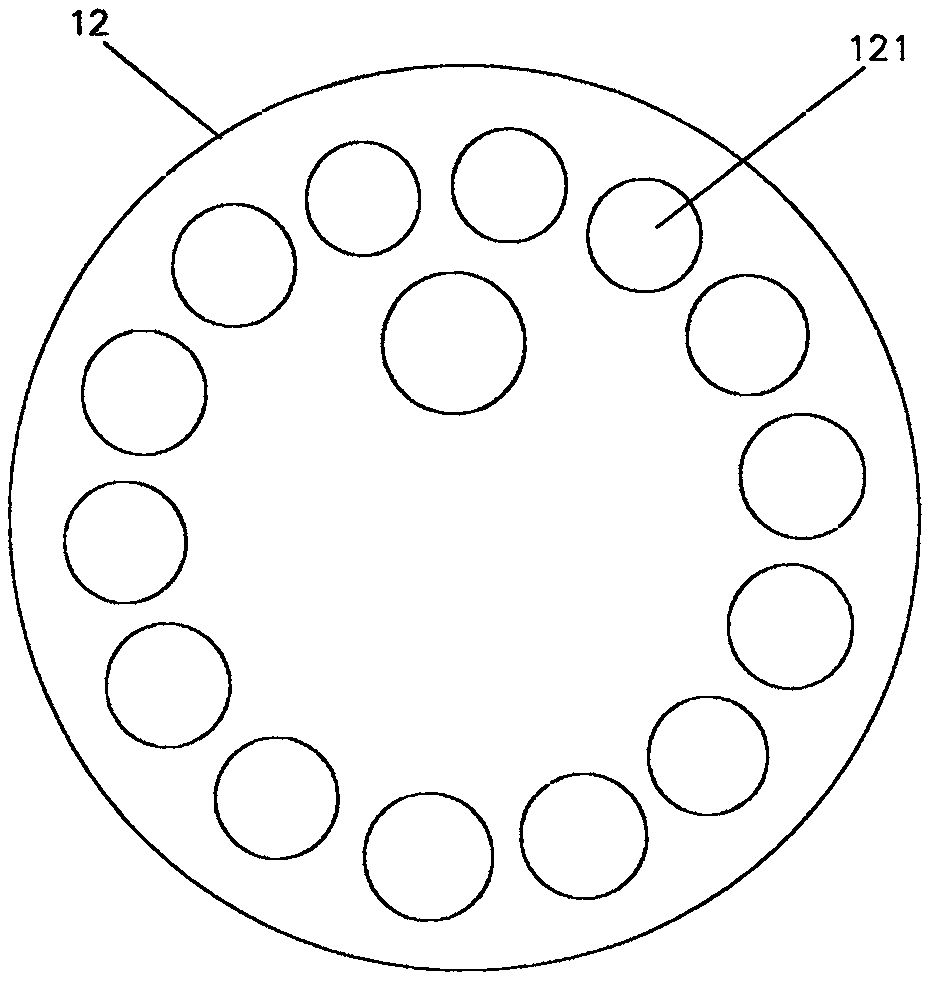
[0020] Implementation column, such as figure 1 , figure 2 , image 3 , Figure 4 , Figure 5 with Image 6 Shown: a three-dimensional code bolt wall core lock, which is composed of a three-dimensional code bolt lock core 1, a lock tube 4 and a screw tube 5, wherein the three-dimensional code bolt lock core 1 part includes a lock code screen 12, a plug honeycomb 13, a screw Shaft 3, lock code 11, plug 14 and spring 15, code lock screen 12 and plug honeycomb 13 are closely attached to each other, and code lock screen 12 is arranged in a two-dimensional manner, with many openings that are thin at the front and thick at the back. The through holes 121 are thicker at the front and thinner in order to prevent the lock code 11 from coming out of the lock code screen 12. These holes 121 are equipped with various code numbers of lock codes 11 to form a three-dimensional layout of the lock code 11. The lock code 11 is The needle cylinder is thin in the front and thick in the back,...


PUM


Abstract

The invention relates to a three-dimensional code bolt wall core lock, and relates to a lockset. In order to overcome the defects that an existing mechanical lock is low in secret key quantity, low inlock core material strength, and weak in lock-tongue way, a traditional axis-type lock core is abandoned, in the three dimensions of a space, lock codes and key codes are fully laid out, a key code needle rod is directly used for pushing a lock code needle rod, and the lock core with the high secret key quantity above trillion and the high strength is achieved. As for the adopted lock core technology, a lock code sieve and a plug honeycomb are closely adjacent, the lock code sieve is provided with a plurality of holes in an arrayed mode according to the two-dimensional mode, the lock codes with multiple code numbers are mounted in the holes, and the three-dimensional layout of the lock codes is formed; and the plug honeycomb is also provided with a plurality of nests in an arrayed mode according to the two-dimensional mode, plugs and springs are mounted in the nests, the lock code sieve is connected with a screw shaft rod which is divided into a shaft rod part and a screw part, the appearance of the honeycomb is polygonal and is matched with an axial hole of a lock pipe in a corresponding mode, the screw part and the screw pipe are engaged and fixed, the screw pipe is inserted into a wall core, and the lock pipe is fixedly connected with the door edge.

Description

technical field [0001] The invention relates to a lock, especially a lock core with a lock code and a key code arranged in three-dimensional space, which is inserted into a wall core in a spiral manner. Background technique [0002] At present, mechanical locks are mainly pin locks and blade locks with key slots. Because the processing of key slots is difficult, the material of the lock cylinder can only use low-strength brass. The existing pin lock cylinder uses an axial lock cylinder. This requires that there must be a key slot and a key handle rod, the pins are arranged in a linear arrangement, and the key teeth are also arranged in a linear manner. The concave and convex angle of the key teeth must be less than about 45 degrees to facilitate insertion into the lock cylinder, so that the longest pin and the shortest pin The differential length cannot be much larger than the diameter of the marbles, which greatly limits the number of marbles and the number of marbles, usua...

Claims


Application Information

Patent Timeline
IPC IPC(8): E05B27/10E05B19/08
CPCE05B19/0017E05B27/00E05B27/10
Inventor 武思军
Owner 武思军
Why Eureka
Try Eureka