FPGA-based method and system for measuring add-carry chain delay

An addition and carry chain and measurement method technology, applied in the direction of measuring electricity, measuring devices, measuring electrical variables, etc., can solve problems such as lack of accuracy, inability to respond to delay time differences, real-time adjustment of working voltage, etc., and achieve accurate results.

Active Publication Date: 2019-12-10
WUHAN WANJI INFORMATION TECH
View PDF10 Cites 0 Cited by
  • Summary
  • Abstract
  • Description
  • Claims
  • Application Information

AI Technical Summary

Problems solved by technology

In actual situations, the measured number of carry chains is not a fixed value, and even needs to be expressed in decimals, so the average measurement method also needs to repeat the measurement many times, so as to provide higher-precision calibration. This method can be used during system operation. In real-time measurement, but it cannot reflect the difference in the delay time of each carry chain, and the accuracy is lacking
[0005] The BIN-by-BIN method needs to measure the delay time of each carry chain, which is usually measured by the code density method. The method is as follows: a square wave signal that is not related to the sampling clock is generated outside the system as the Hit signal. Each rising edge of , triggers a time marker measurement. Since the Hit signal is not correlated with the sampling clock, after multiple measurements, the triggering moments of the Hit signal should be evenly distributed within one period of the sampling clock, so the flip-flop array is latched. In the running state of the carry chain, the positions of its rising or falling edges should be equally probable distributed in one cycle. Conversely, the number of HITs captured by each carry chain should be proportional to the delay time of the carry chain. The delay time of each carry chain is measured, but this method can only be measured before the system is running, and cannot be adjusted in real time according to the ambient temperature and operating voltage

Method used


Image

  • FPGA-based method and system for measuring add-carry chain delay
  • FPGA-based method and system for measuring add-carry chain delay
  • FPGA-based method and system for measuring add-carry chain delay

Examples


Embodiment approach

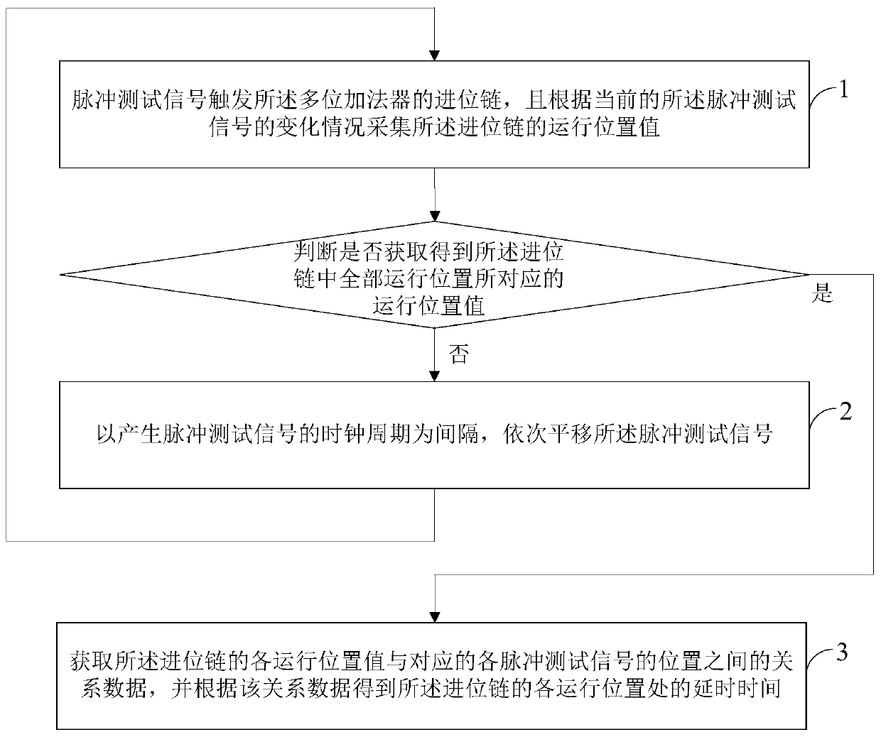
[0058] Embodiment 1 of the present invention provides the first specific implementation of a method for measuring the delay of the addition and carry chain based on FPGA, see figure 1 , the measurement method of the delay of the addition carry chain based on FPGA is used to measure the delay of the addition carry chain in the idle time that the multi-bit adder in the FPGA carries out actual timing measurement, and the measurement method specifically includes as follows content:

[0059] Step 1: The pulse test signal triggers the carry chain of the multi-bit adder, and collects the running position value of the carry chain according to the current change of the pulse test signal.

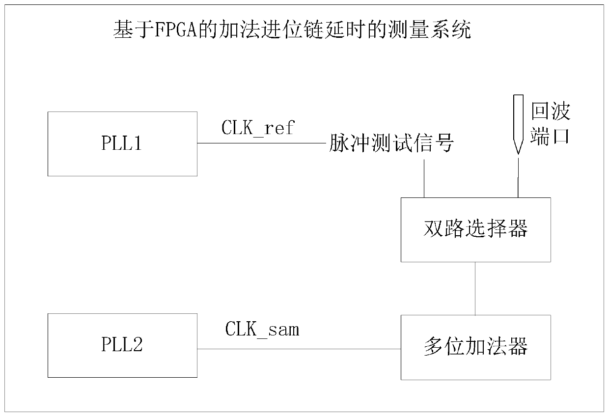
[0060] In step 1, the measurement method of the delay of the addition carry chain based on FPGA can be realized by applying a measurement system of the delay of addition carry chain based on FPGA, and the measurement system specifically includes: the reference clock CLK_ref in the FPGA , sampling cl...


PUM


Abstract

The invention provides a method and system for measuring the delay of an addition carry chain based on FPGA. The measurement method includes: a pulse test signal triggers the carry chain of a multi-bit adder, and collects the carry chain according to the change of the current pulse test signal The running position value of the pulse test signal; at the interval of the clock cycle that generates the pulse test signal, the pulse test signal is shifted in turn, and after each shift of the pulse test signal, it is re-triggered and the running position value is obtained until all the running positions in the carry chain are obtained The corresponding operating position value; and obtain the relational data between each operating position value of the carry chain and the corresponding position of each pulse test signal, and obtain the delay time at each operating position of the carry chain according to the relational data. The invention can measure the delay time between different carry chains in real time, avoid the influence of temperature and voltage fluctuations, and further realize the high-precision timing of TDC components based on FPGA.

Description

technical field [0001] The invention relates to the technical field of digital measurement, in particular to an FPGA-based measurement method and system for adding and carrying chain delay. Background technique [0002] In the FPGA-based time-to-digital conversion TDC design architecture, the use of carry chain delay chains to obtain high-precision delay information has been widely used. However, this TDC based on the carry chain structure is limited by the uniformity of the carry chain. The ambient temperature and different FPGAs will change the delay of the carry chain, which is the main limiting factor to improve the performance of TDC. Therefore, it is necessary to measure the delay time of the carry chain in real time. [0003] At present, the carry chain measurement methods are mainly divided into analog and digital. Among them, the analog method is mainly realized by the feedback circuit, which is often used in integrated chips, while the carry chain measurement in th...

Claims


Application Information

Patent Timeline
Patent Type & Authority Patents(China)
IPC IPC(8): G01R31/28G01R31/317
CPCG01R31/2882G01R31/31725
Inventor 杨明惠周行杨俊
Owner WUHAN WANJI INFORMATION TECH
Why Eureka
Try Eureka