Unlock instant, AI-driven research and patent intelligence for your innovation.

Connector and connector assembly

A connector assembly and connector technology, which are applied in the direction of connection, parts of connection devices, fixed connections, etc., can solve the problems of limiting operating bandwidth, causing resonance, coupling enhancement, etc., to achieve the effect of suppressing resonance.

Inactive Publication Date: 2018-05-25
TYCO ELECTRONICS (SHANGHAI) CO LTD
View PDF7 Cites 8 Cited by
  • Summary
  • Abstract
  • Description
  • Claims
  • Application Information

AI Technical Summary

Problems solved by technology

However, when the first connector has two rows of adjacent conductive terminals, the excessively long conductive terminals will cause the coupling between the two adjacent rows of conductive terminals of the first connector to be enhanced, so that the Resonance is induced between two adjacent rows of conductive terminals
The greater the length of the two adjacent rows of conductive terminals, the stronger the coupling between the two adjacent rows of conductive terminals, and the stronger the resonance between the adjacent two rows of conductive terminals. It will affect the work of the paired first connector and second connector, and limit its working bandwidth

Method used


Image

  • Connector and connector assembly
  • Connector and connector assembly
  • Connector and connector assembly

Examples


Embodiment Construction

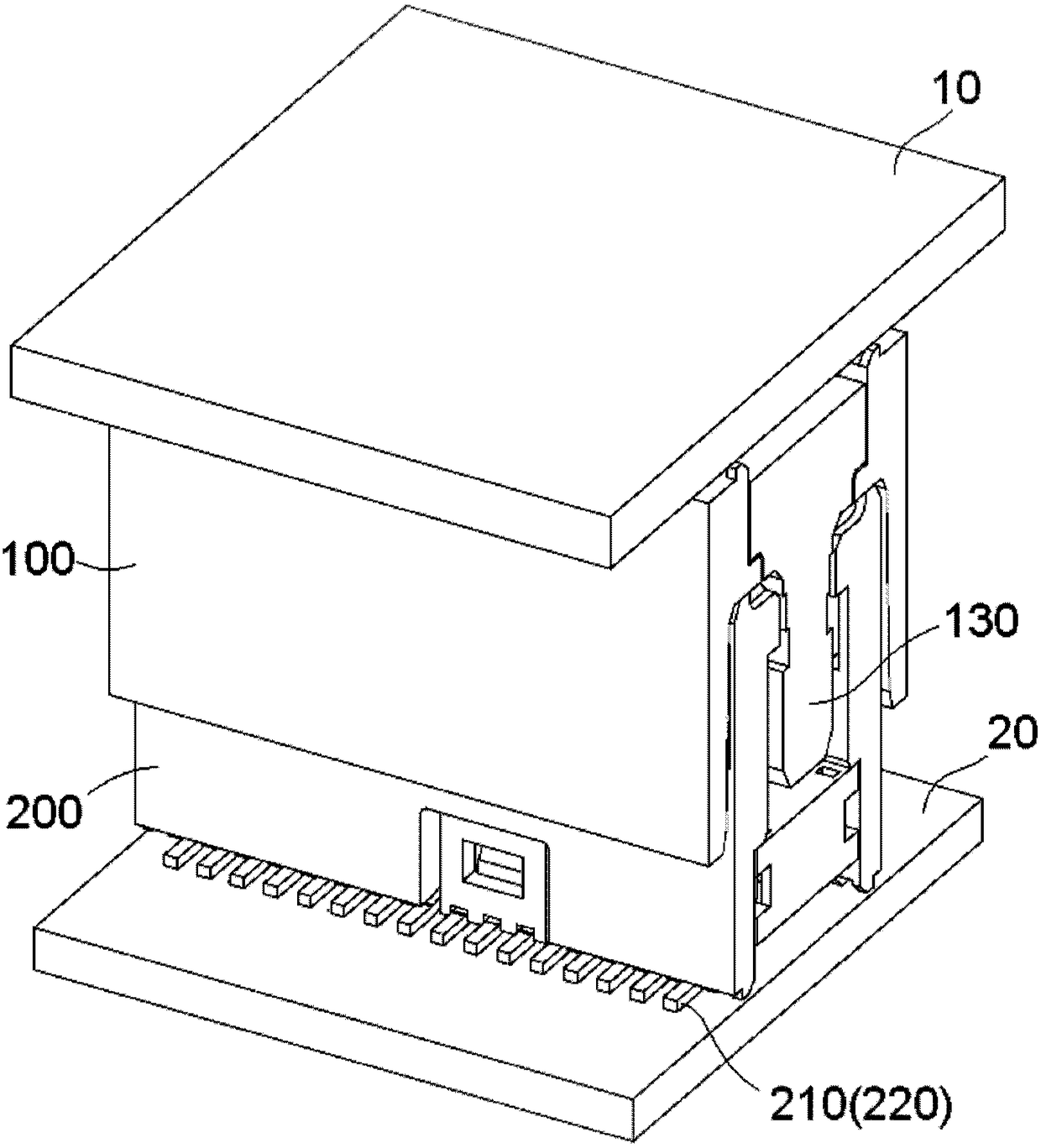
[0028] The technical solutions of the present invention will be further specifically described below through the embodiments and in conjunction with the accompanying drawings. In the specification, the same or similar reference numerals designate the same or similar components. The following description of the embodiments of the present invention with reference to the accompanying drawings is intended to explain the general inventive concept of the present invention, but should not be construed as a limitation of the present invention.

[0029] In addition, in the following detailed description, for purposes of explanation, numerous specific details are set forth in order to provide a comprehensive understanding of the embodiments of the present disclosure. It may be evident, however, that one or more embodiments may be practiced without these specific details. In other instances, well-known structures and devices are shown in diagrammatic form to simplify the drawings.

[0...


PUM


Abstract

The invention discloses a connector. The connector comprises a casing, rows of terminals and an insert tongue; the rows of terminals include one row of first terminals and one row of second terminalsadjusted to the row of first terminals at least. Parts where the row of first terminals makes contact with the row of second terminals are maintained in the first and second sides of the insert tonguerespectively. The tail portions of the contact parts of at least part of the first terminals are disconnected from the corresponding first terminals, and the tail ports of the contact parts of secondterminals corresponding to the part of the first terminals are disconnected from the corresponding second terminals. The tail portions of the contact parts of at least part of the terminals in the two adjacent rows of terminals are disconnected from the corresponding terminals, so that the effective conductive length of the corresponding terminals can be reduced, and resonance between the two adjacent rows of terminals can be inhibited effectively. Thus, the tail portions disconnected from the corresponding terminals can scratch terminals of a paired connector, and it is ensured that the scratching distance between the connector and the paired connector is sufficient.

Description

technical field [0001] The present invention relates to a connector and a connector assembly. Background technique [0002] Generally, among two connectors (maybe referred to as a first connector and a second connector) adapted to be mated with each other, for example, the first connector has a tongue-shaped plug, and the second connector has an insertion cavity, The tongue-shaped plug is adapted to be inserted into the insertion cavity. The conductive terminals of the first connector are fixedly held on the tongue plug. The elastic arm of the conductive terminal of the second connector protrudes into the insertion cavity so as to make elastic electrical contact with the conductive terminal of the first connector on the tongue-shaped plug inserted into the insertion cavity. [0003] In the prior art, during the mating process of the first connector and the second connector, the electrical contact of the elastic arm of the conductive terminal of the second connector is in e...

Claims


Application Information

Patent Timeline
IPC IPC(8): H01R13/04H01R13/115
CPCH01R13/04H01R13/115H01R12/73H01R13/6471H01R12/716H01R12/57H01R13/405H01R13/24
Inventor 黄亮
Owner TYCO ELECTRONICS (SHANGHAI) CO LTD