Linear actuator

A linear actuator and moving body technology, which is applied in the direction of magnetic objects, electric components, non-rotational vibration suppression, etc., can solve problems such as resonance and inability to control the movement of movable bodies

Active Publication Date: 2016-11-09
SANKYO SEIKI MFG CO LTD
View PDF7 Cites 14 Cited by
  • Summary
  • Abstract
  • Description
  • Claims
  • Application Information

AI Technical Summary

Problems solved by technology

[0009] As in the structure described in Patent Document 1, when the movable body is driven by the magnetic drive mechanism and the coil spring is brought into contact with the movable body, there is a problem that the frequency of reciprocating movement of the movable body may vary depending on the frequency of the movable body. Resonance occurs, and the movement of movable bodies cannot be controlled

Method used


Image

  • Linear actuator
  • Linear actuator
  • Linear actuator

Examples


Embodiment approach 1

[0048] (the whole frame)

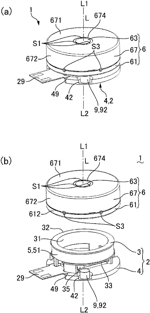
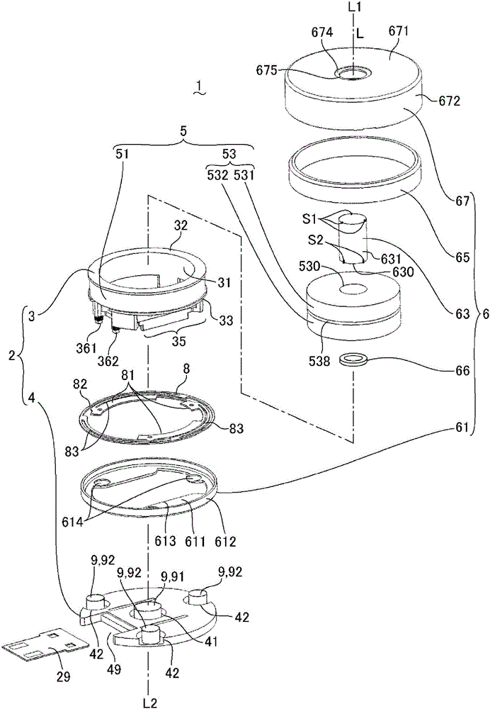
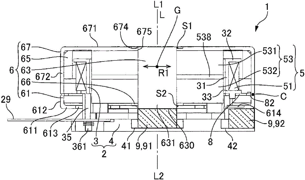
[0049] figure 1 It is explanatory drawing of the linear actuator concerning Embodiment 1 of this invention, figure 1 (a) is a perspective view of the linear actuator, figure 1 (b) is an exploded perspective view of the linear actuator. figure 2 It is an exploded perspective view in which the linear actuator according to Embodiment 1 of the present invention is disassembled in detail. image 3 It is a cross-sectional view of the linear actuator according to Embodiment 1 of the present invention.

[0050] Such as figure 1 , figure 2 as well as image 3 As shown, the linear actuator 1 of this embodiment has a fixed body 2, a movable body 6, and a spring member 8 connecting the movable body 6 and the fixed body 2, and the spring member 8 supports the movable body 6 in the axis L direction. To be able to move relative to the fixed body 2. Further, the linear actuator 1 has a magnetic drive mechanism 5 that drives the movable body 6 in the axis L...

Embodiment approach 2

[0099] (the whole frame)

[0100] Figure 4 It is explanatory drawing of the linear actuator concerning Embodiment 2 of this invention (1st and 2nd invention), figure 2 (a) is a perspective view of the linear actuator, figure 2 (b) is an exploded perspective view of the linear actuator. Figure 5 It is an exploded perspective view in which the linear actuator according to Embodiment 2 of the present invention is disassembled in detail. Figure 6 It is a cross-sectional view of the linear actuator according to Embodiment 2 of the present invention. In addition, since the basic structure of this embodiment is the same as that of Embodiment 1, the same code|symbol is attached|subjected to a common part. In addition, as in the above-mentioned first embodiment, since the basic configuration of the second invention is substantially the same as that of the first invention, the same drawings will be used for description, and the same symbols will be assigned to common parts.

...


PUM


Abstract

The present application provides a linear actuator which uses a magnetic drive mechanism to drive a movable element and which can effectively suppress resonance of the movable element even when a spring member is connected thereto. Specifically, this linear actuator (1) is provided with: a stator (2), a movable element (6), a spring member (8) connected to the movable element (6) and the stator (2), and a magnetic drive mechanism (5) which drives the movable element (6) along an axis (L). Further, between the stator (2) and the movable element (6), gel-like damper members (9) that comprise silicone gel, etc., are arranged in positions on the axis (L) and/or positions surrounding the axis (L). For example, in the stator (2), the gel-like damper members (9) may be arranged in positions along the axis (L) between the movable element (6) and a base (4) opposite the movable element (6). The gel-like damper members (9) include a first gel-like damper member (91) positioned on the axis (L), and second gel-like damper members (92) positioned so as to surround the axis (L).

Description

technical field [0001] The invention relates to a linear actuator with a magnetic drive mechanism. Background technique [0002] As a linear actuator, the following structure has been proposed: when driving the plunger as a movable body in the axial direction, a magnetic drive mechanism including a coil and a permanent magnet is provided, and a coil spring coaxial with the plunger is provided. contact with the plunger (refer to Patent Document 1). [0003] In addition, as a linear actuator, there has been proposed a structure in which a magnetic drive mechanism having a coil and a permanent magnet is provided when the movable body is driven in the axial direction, and a magnetic drive mechanism is arranged between the movable body and the fixed body. An elastic member composed of a thin plate-shaped elastic member and a coil spring (refer to Patent Document 2). [0004] prior art literature [0005] patent documents [0006] Patent Document 1: Japanese Patent Laid-Open N...

Claims


Application Information

Patent Timeline
Patent Type & Authority Applications(China)
IPC IPC(8): H02K33/02F16F15/04
CPCH01F7/088H01F7/1615H02K1/34H02K5/24H02K7/086H02K33/02H02K2213/03H02K33/16H02K1/12
Inventor 武田正北原裕士须江猛
Owner SANKYO SEIKI MFG CO LTD
Why Eureka
Try Eureka