Driver for optical deflector using two modified syncronous saw-tooth drive voltages and method for setting the same

a technology of drive voltage and optical deflector, which is applied in the direction of piezoelectric/electrostrictive/magnetostrictive devices, piezoelectric/electrostriction/magnetostriction machines, instruments, etc., can solve the problems of inability to use an image display apparatus such as a projector, difficult to rock the mirror at a larger deflection angle, and inability to achieve the effect of a small effective scanning period

Active Publication Date: 2012-09-27
STANLEY ELECTRIC CO LTD
View PDF1 Cites 14 Cited by
  • Summary
  • Abstract
  • Description
  • Claims
  • Application Information

AI Technical Summary

Benefits of technology

[0014]According to the presently disclosed subject matter, since use is made of modified synchronous saw-tooth waves, the deflection angle can be linearly changed for a longer period, so that the optical deflector according to the presently disclosed subject matter can be applied to an image display apparatus such as a projector. Also, the resonance of the harmonic frequency components of the first and second drive voltages with the natural frequency components of the mechanically-vibrating system of the mirror can be suppressed.

Problems solved by technology

In this case, however, since the mechanically-vibrating system of the mirror including the outer piezoelectric actuators is hardened, it would be difficult to rock the mirror at a larger deflection angle.
In this case, however, a linearly-deflected period within one period of the synchronous sinusoidal-wave drive voltages where the deflection angle is linearly changed becomes too small, i.e., an effective scanning period becomes too small, so it is not practical in an image display apparatus such as a projector to use such an optical deflector.

Method used


Image

  • Driver for optical deflector using two modified syncronous saw-tooth drive voltages and method for setting the same
  • Driver for optical deflector using two modified syncronous saw-tooth drive voltages and method for setting the same
  • Driver for optical deflector using two modified syncronous saw-tooth drive voltages and method for setting the same

Examples


Embodiment Construction

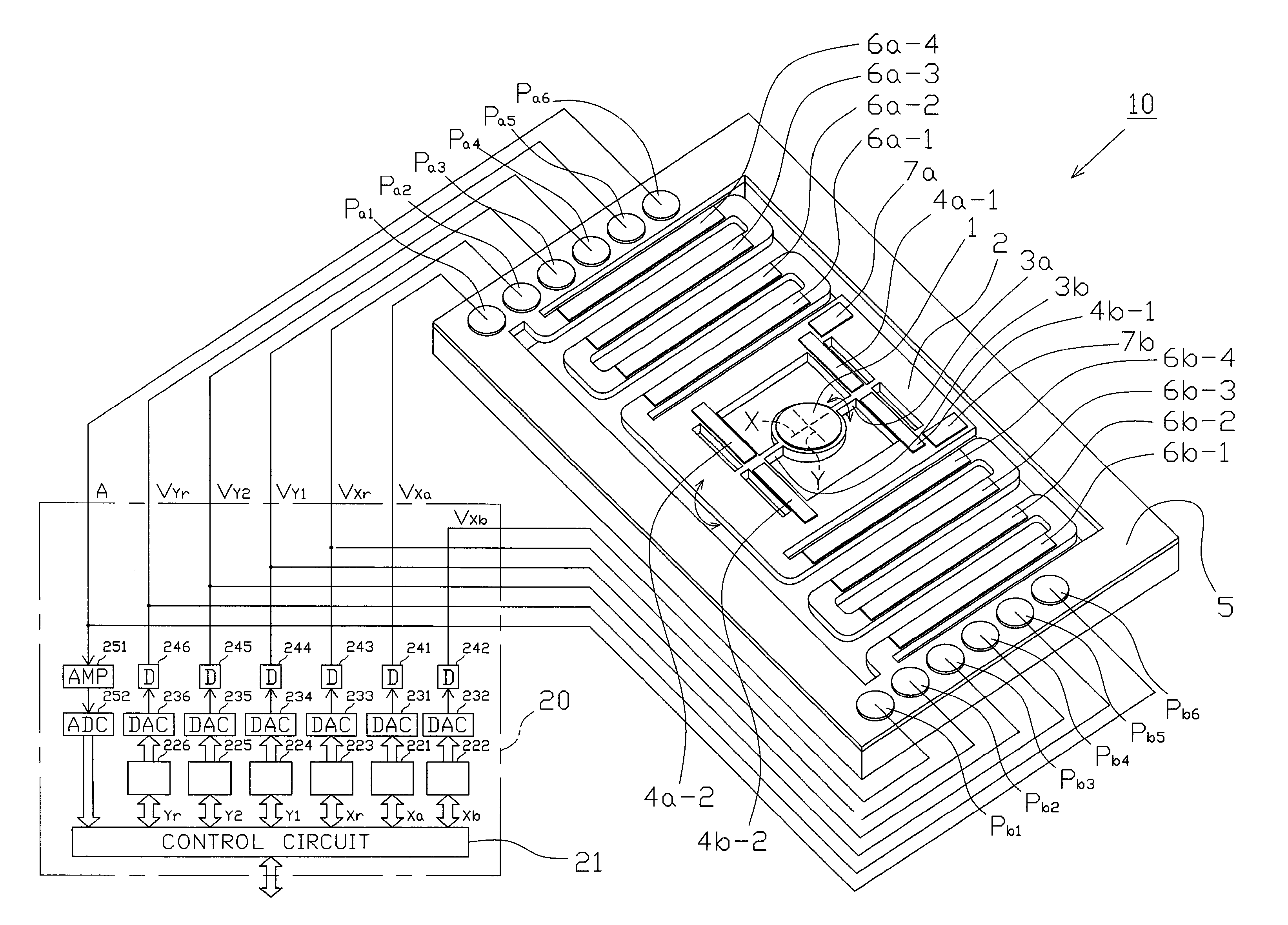
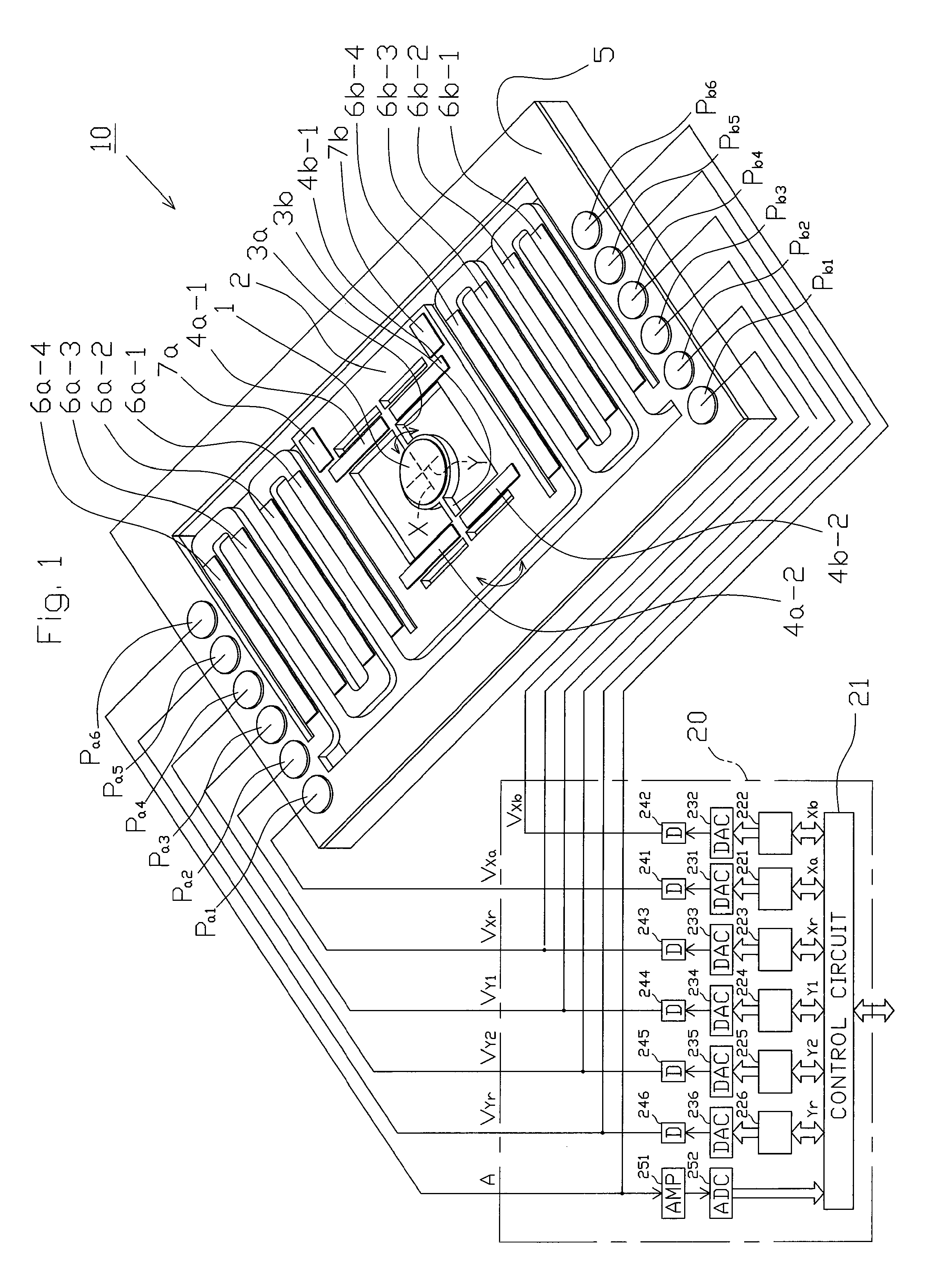
[0032]In FIG. 1, which illustrates an embodiment of the driver for driving an optical deflector according to the presently disclosed subject matter, an optical deflector 10 and its driver 20 are provided.

[0033]The optical deflector 10 is constructed by a circular mirror 1 for reflecting an incident light, a movable frame 2 surrounding the mirror 1 for supporting the mirror 1 through a pair of torsion bars 3a and 3b, inner piezoelectric actuators 4a-1, 4a-2, 4b-1 and 4b-2 fixed between the movable frame 2 and the torsion bars 3a and 3b and serving as cantilevers for rocking the mirror 1 through the torsion bars 3a and 3b with respect to an X-axis of the mirror 1, a support body 5 surrounding the movable frame 2, outer piezoelectric actuators 6a-1, 6a-2, 6a-3 and 6a-4 and 6b-1, 6b-2, 6b-3 and 6b-4 fixed between the support body 5 and the movable frame 2 and serving as cantilevers for rocking the mirror 1 through the movable frame 2 with respect to a Y-axis of the mirror 1 perpendicula...


PUM


Abstract

In an optical deflector including a mirror, a movable frame supporting the mirror, a support body surrounding the movable frame, and a first group of piezoelectric actuators and a second group of piezoelectric actuators alternating with the first group of piezoelectric actuators, a driver combines first and second original saw-tooth waves having the same waveform into first saw-tooth waves, and applies a first drive voltage having the first saw-tooth waves to the first group of piezoelectric actuators. The driver applies a second drive voltage having second saw-tooth waves opposite in phase with the first saw-tooth waves to the second group of piezoelectric actuators.

Description

[0001]This application claims the priority benefit under 35 U.S.C. §119 to Japanese Patent Application No. JP2011-062919 filed on Mar. 22, 2011, which disclosure is hereby incorporated in its entirety by reference.BACKGROUND[0002]1. Field[0003]The presently disclosed subject matter relates to a driver for driving an optical deflector and a method for setting drive voltages therefor.[0004]2. Description of the Related Art[0005]A prior art two-dimensional optical deflector is constructed by a mirror; a movable frame surrounding the mirror for supporting the mirror through a pair of torsion bars; inner piezoelectric actuators fixed between the movable frame and the torsion bars and serving as cantilevers for rocking the mirror through the torsion bars with respect to an X-axis of the mirror; a support body surrounding the movable frame; and meander-shaped outer piezoelectric actuators fixed between the support body and the movable frame and serving as cantilevers for rocking the mirror...

Claims


Application Information

Patent Timeline
Patent Type & Authority Applications(United States)
IPC IPC(8): H01L41/09
CPCH02N2/0075G02B26/0858G02B26/10
Inventor AIMONO, TAKANORI
Owner STANLEY ELECTRIC CO LTD
Why Eureka
Try Eureka