Clutch device having a clutch damper and dual-mass flywheel assembly

a technology of clutch damper and flywheel, which is applied in the direction of mechanical actuated clutches, friction linings, couplings, etc., can solve the problems of excessively large, vibration, and vibration of the transmission system of the vehicle, and achieves simple structure, low speed range, and suppression of resonance vibrations.

Inactive Publication Date: 2007-03-27
EXEDY CORP
View PDF67 Cites 14 Cited by
  • Summary
  • Abstract
  • Description
  • Claims
  • Application Information

AI Technical Summary

Benefits of technology

[0020]An object of the present invention is to provide a clutch device having a flywheel coupled to a shaft of a transmission via a clutch disk assembly or the like, and particularly to suppress resonance vibrations in a low speed range by a simple structure.

Problems solved by technology

A power transmission system of a vehicle causes unwanted noises and vibrations such as gear collision noises of a drive system and muffled noises during driving.
This may cause excessively large torque vibrations that can result in the breaking of the damper mechanism.
Alternatively, large noises and vibrations may occur.
However, this lock mechanism complicates the structure, and increases the number of parts.
Thereby, the torsional vibrations are rapidly damped.
Accordingly, the frictional resistance generating mechanism also requires many parts and a complicated structure as a whole.
Thus, this reaction causes excessive torque to be applied to the tires so that large longitudinal vibrations transitionally occur to vibrate the vehicle body longitudinally to a large extent.
This complicates a structure, and requires a difficult assembly operation for ensuring the angular space.
Therefore, these windows are prone to transmit vibrational noises as well as sliding noises and others of the elastic members from the engine side to the transmission side.

Method used


Image

  • Clutch device having a clutch damper and dual-mass flywheel assembly
  • Clutch device having a clutch damper and dual-mass flywheel assembly
  • Clutch device having a clutch damper and dual-mass flywheel assembly

Examples


Embodiment Construction

[0078]Selected embodiments of the present invention will now be explained with reference to the drawings. It will be apparent to those skilled in the art from this disclosure that the following description of the embodiments of the present invention is provided for illustration only, and not for the purpose of limiting the invention as defined by the appended claims and their equivalents.

[0079](1) Structure

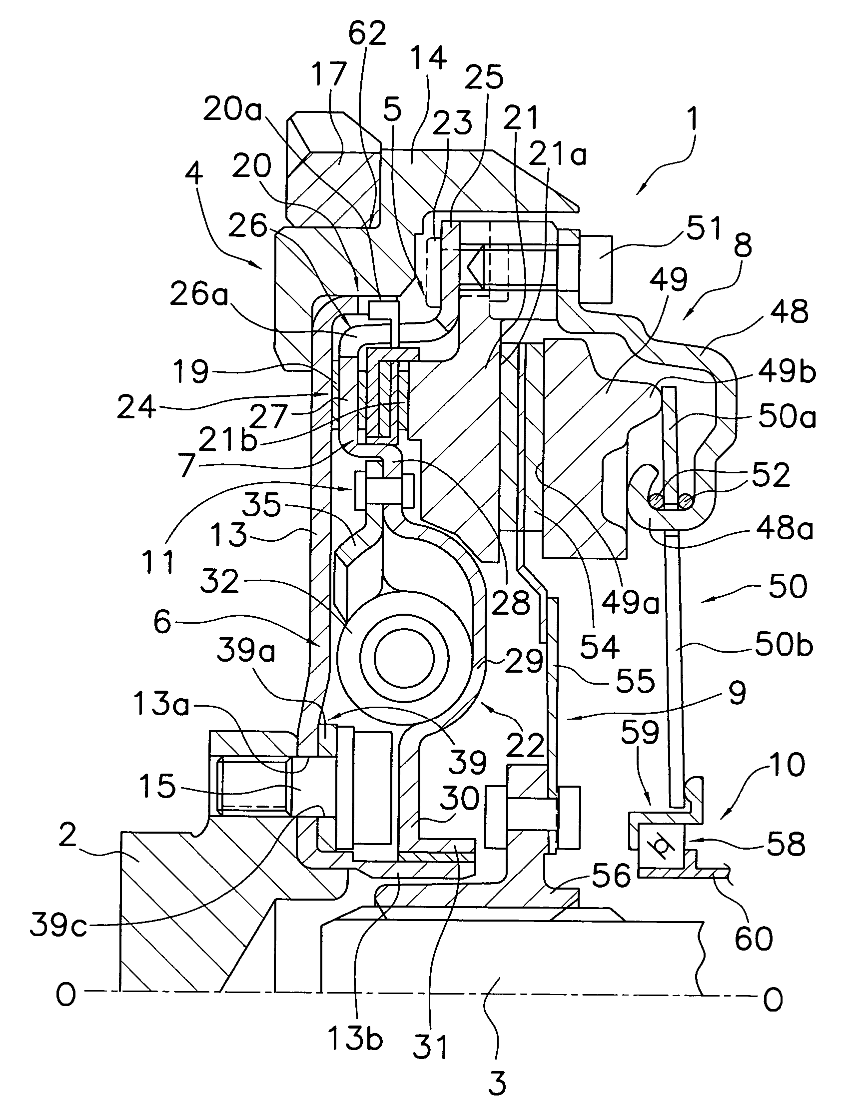
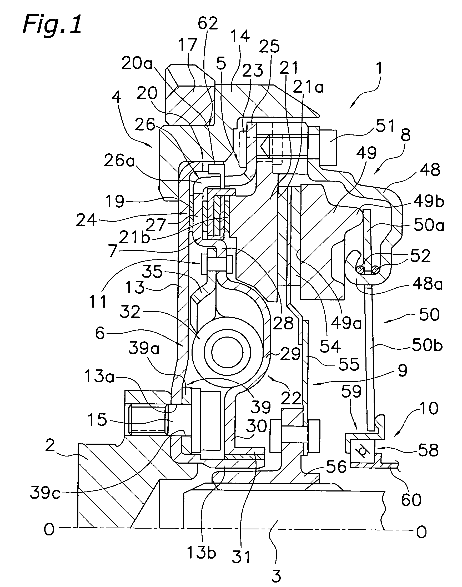
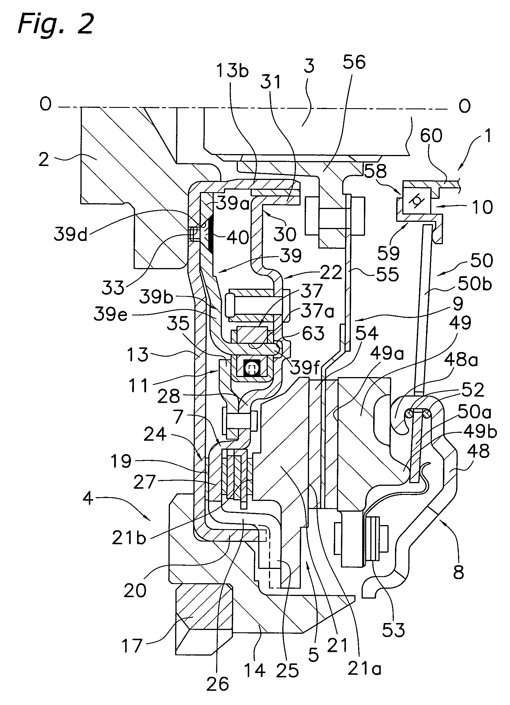
[0080]Referring initially to FIGS. 1 and 2, a clutch device 1 in accordance with a preferred embodiment of the present invention is primarily formed of a first flywheel assembly 4, a second flywheel assembly 5, a clutch cover assembly 8, a clutch disk assembly 9, and a release device 10. The first and second flywheel assemblies 4 and 5 are combined to form a flywheel damper 11 including a damper mechanism 6.

[0081]An engine (not shown) is arranged on the left side in FIGS. 1 and 2, and a transmission (not shown) is arranged on the right side. The clutch device 1 is a device that re...


PUM


Abstract

In a clutch device 1, a second flywheel assembly 5 is axially movable within a predetermined range relative to a crankshaft 2, and a flywheel 21 has a friction surface 21a on a side remote from an engine. The damper mechanism 6 elastically couples the flywheel 21 to the crankshaft 2. The clutch disk assembly 9 has a friction facing 54 neighboring the first friction surface 21a. The clutch cover assembly 8 is attached to the flywheel 21, and biases the friction facing 54 toward the first friction surface 21a. The release device 10 applies an axial load directed toward the engine to the clutch cover assembly 8, and thereby releases the load toward the friction facing 54. The relative rotation suppressing mechanism 24 couples the second flywheel assembly 5 to the disk-like member 13 when the clutch cover assembly 8 receives the axial load directed toward the engine.

Description

BACKGROUND OF THE INVENTION[0001]1. Field of the Invention[0002]The invention relates to a clutch device having a flywheel. More specifically, the present invention relates to a clutch device, in which the flywheel has a friction surface to facilitate clutch coupling to a frictional coupling portion of a clutch disk assembly. The present invention also relates to a frictional resistance generating mechanism generating a hysteresis torque for damping torsional vibrations.[0003]2. Background Information[0004]Conventionally, a flywheel is attached to a crankshaft of an engine for absorbing vibrations caused by variations in engine combustion. Further, a clutch device is arranged on a transmission side (i.e., in a position axially shifted toward the transmission) with respect to the flywheel. The clutch device usually includes a clutch disk assembly coupled to an input shaft of the transmission and a clutch cover assembly for biasing the frictional coupling portion of the clutch disk as...

Claims


Application Information

Patent Timeline
Patent Type & Authority Patents(United States)
IPC IPC(8): F16F15/30F16D13/60F16F15/139
CPCF16F15/139F16D13/50F16D2013/703F16D13/60
Inventor FUKUSHIMA, HIROTAKA
Owner EXEDY CORP
Why Eureka
Try Eureka