
A gas distributor for a circulation scrubber and its design method
A gas distributor and distributor technology, applied in separation methods, using liquid separating agents, chemical instruments and methods, etc., can solve the problems of non-circulating flow, short residence time, and short ash residence time.
- Summary
- Abstract
- Description
- Claims
- Application Information
AI Technical Summary
Problems solved by technology
Method used
Image

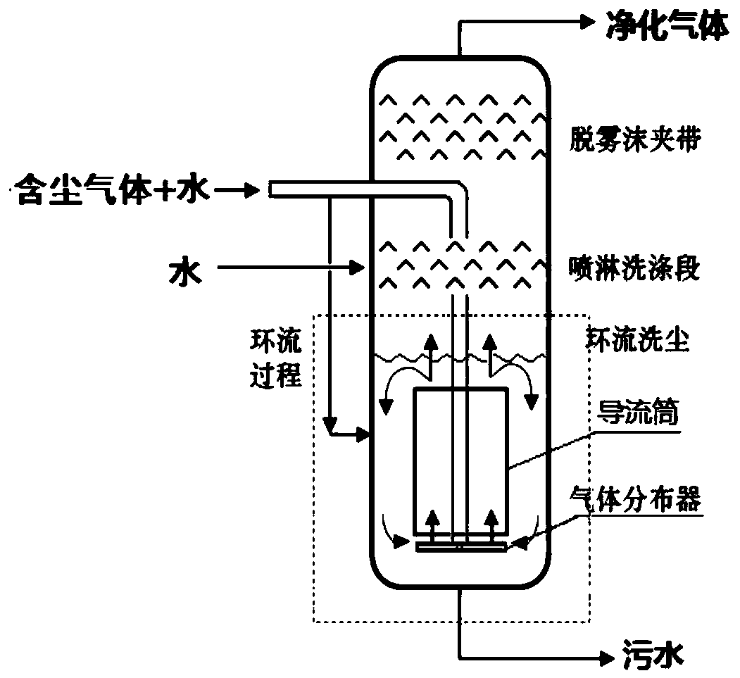
Examples
Embodiment 1
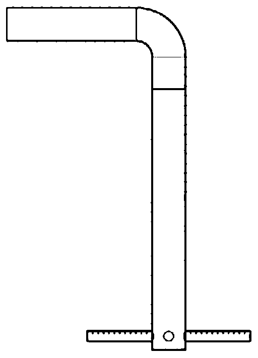
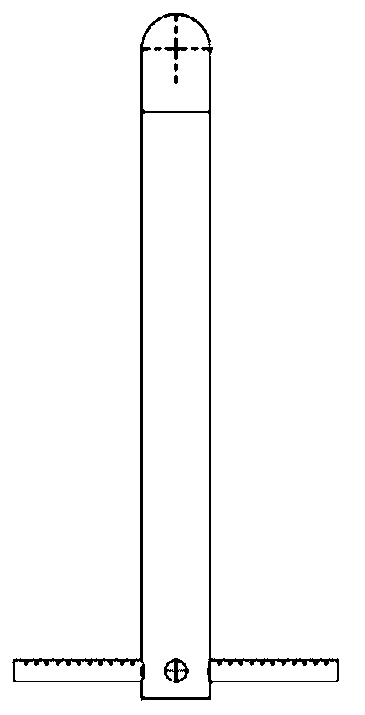
[0087] This embodiment provides a kind of dedusting gas distributor used in conjunction with the circulating water washing tower, its structure is as follows Figure 3a-Figure 3c , Figure 8 shown.
[0088] This gas distributor is made up of central inlet pipe 1 and four branch pipes 2, wherein, the end of central inlet pipe 1 is provided with blind plate, and, this blind plate is provided with drain hole 4, as Figure 3c As shown, the bottom end of the branch pipe 2 is also provided with a drain hole 4, and the above drain hole is Figure 12c circular through hole shown;
[0089] The four branch pipes 2 are all straight pipes, which are evenly distributed around the central air intake pipe 1 in a horizontal arrangement and diverge outward to form a branched structure;
[0090] The pipe wall of the branch pipe 2 is provided with a gas injection hole 3, such as Figure 8 As shown, the gas injection hole 3 is as Figure 12a The vertical through hole shown; the diameter of t...
Embodiment 2
[0107] This embodiment provides a gas distributor, its structure is as follows Figure 4a-Figure 4c , Figure 10 shown.
[0108] The gas injection holes provided on the branch pipe wall of this gas distributor are contraction type short tube nozzles 6, such as Figure 10 Shown, the sectional view of contraction type short pipe nozzle 6 is as Figure 12b As shown, the inlet aperture of the contracting short tube nozzle 6 is 6mm, and the outlet aperture is 4mm.
[0109] Other structures of the gas distributor are the same as the gas distributor in Example 1.
Embodiment 3
[0111] A kind of dedusting gas distributor used in cooperation with the circulating water washing tower provided by this embodiment, its structure is as follows Figure 5a-5c shown.
[0112] This gas distributor is made up of central inlet pipe 1 and four branch pipes 2, wherein, the end of central inlet pipe 1 is provided with blind plate, and, this blind plate is provided with drain hole, as Figure 5c As shown, the drain hole is Figure 12c circular through hole shown;
[0113] The main parts of the four branch pipes 2 are straight pipes, and the part connected to the central air intake pipe 1 is a small section of horizontal section; Appropriate acute angle) is evenly distributed around the central air intake pipe 1 and diverges outwards to form a dendritic structure; the bottom of the horizontal section of the branch pipe 2 is provided with a drain hole 4, such as Figure 5a , Figure 5b As shown, in addition, a drain hole 4 is provided at the end of the straight pipe...
PUM
 Abstract
Description
Claims
Application Information