Gas distributor for circulating-flow scrubbing tower and design method of gas distributor

A technology of gas distributor and washing tower, which is applied in the direction of separation methods, chemical instruments and methods, and the use of liquid separation agents, etc., which can solve the problems of inability to circulate, continuous discharge of solid slag, and multi-layer gas distribution branch pipe structure. Problems such as complex systems of solid particle deposition

Active Publication Date: 2018-05-29
CHINA UNIV OF PETROLEUM (BEIJING)
View PDF13 Cites 8 Cited by
  • Summary
  • Abstract
  • Description
  • Claims
  • Application Information

AI Technical Summary

Problems solved by technology

[0010] 2. The ash wrapped in some large bubbles in the bubbling bed has a short residence time and cannot be wetted and transferred to the water phase for removal
Because the gas in the bubbling bed is a one-pass type and cannot circulate, the bubbles stay for a short time under the action of buoyancy, which is not conducive to the collapse of the bubbles and the discharge of ash and wetting.
[0011] 3. Wet dust removal involves gas-liquid-solid three-phase, and the continuous discharge of solid residue is difficult
The gas distributor still adopts ring pipes outside, and the multi-layer gas distribution branch pipe structure is not suitable for conveying complex systems containing solid particle deposition
Moreover, the liquid sealing effect of the liquid sealing tank at the bottom of the gas collecting pipe is related to the height of the liquid layer in the tower. For the gas to go back and forth, there must be a considerable liquid sealing height in the liquid sealing tank, and due to the design of the upper and lower layers of the gas distribution branch pipe , the space occupied by the sparger is relatively large, and it is not suitable for wet dust removal that requires rapid phase separation in the sparger

Method used


Image

  • Gas distributor for circulating-flow scrubbing tower and design method of gas distributor
  • Gas distributor for circulating-flow scrubbing tower and design method of gas distributor
  • Gas distributor for circulating-flow scrubbing tower and design method of gas distributor

Examples


Embodiment 1

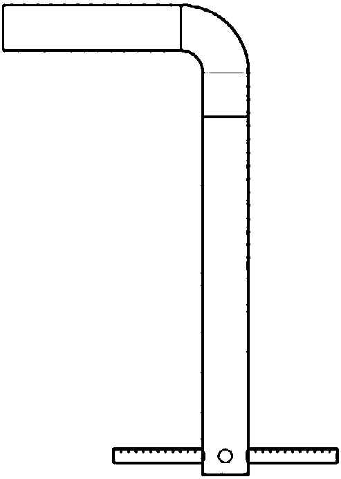
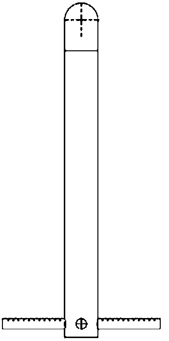
[0087] This embodiment provides a kind of dedusting gas distributor used in conjunction with the circulating water washing tower, its structure is as follows Figure 3a-Figure 3c , Figure 8 shown.

[0088] This gas distributor is made up of central inlet pipe 1 and four branch pipes 2, wherein, the end of central inlet pipe 1 is provided with blind plate, and, this blind plate is provided with drain hole 4, as Figure 3c As shown, the bottom end of the branch pipe 2 is also provided with a drain hole 4, and the above drain hole is Figure 12c circular through hole shown;

[0089] The four branch pipes 2 are all straight pipes, which are evenly distributed around the central air intake pipe 1 in a horizontal arrangement and diverge outward to form a branched structure;

[0090] The pipe wall of the branch pipe 2 is provided with a gas injection hole 3, such as Figure 8 As shown, the gas injection hole 3 is as Figure 12a The vertical through hole shown; the diameter of t...

Embodiment 2

[0107] This embodiment provides a gas distributor, its structure is as follows Figure 4a-Figure 4c , Figure 10 shown.

[0108] The gas injection holes provided on the branch pipe wall of this gas distributor are contraction type short tube nozzles 6, such as Figure 10 Shown, the sectional view of contraction type short pipe nozzle 6 is as Figure 12b As shown, the inlet aperture of the contracting short tube nozzle 6 is 6mm, and the outlet aperture is 4mm.

[0109] Other structures of the gas distributor are the same as the gas distributor in Example 1.

Embodiment 3

[0111] A kind of dedusting gas distributor used in cooperation with the circulating water washing tower provided by this embodiment, its structure is as follows Figure 5a-5c shown.

[0112] This gas distributor is made up of central inlet pipe 1 and four branch pipes 2, wherein, the end of central inlet pipe 1 is provided with blind plate, and, this blind plate is provided with drain hole, as Figure 5c As shown, the drain hole is Figure 12c circular through hole shown;

[0113] The main parts of the four branch pipes 2 are straight pipes, and the part connected to the central air intake pipe 1 is a small section of horizontal section; Appropriate acute angle) is evenly distributed around the central air intake pipe 1 and diverges outwards to form a dendritic structure; the bottom of the horizontal section of the branch pipe 2 is provided with a drain hole 4, such as Figure 5a , Figure 5b As shown, in addition, a drain hole 4 is provided at the end of the straight pipe...


PUM


Abstract

The invention provides a gas distributor for a circulating-flow scrubbing tower and a design method of the gas distributor. The gas distributor is of a branch-shaped distributor structure and is provided with a central gas inlet pipe and at least one branch pipe, wherein the branch pipes are connected with the central gas inlet pipe, a blind plate is arranged at the tail end of the central gas inlet pipe, liquid discharging holes are formed in the blind plate at the tail end of the central gas inlet pipe, and liquid discharging holes are also formed near the lowest ends or the tail ends of thebranch pipes; gas spraying holes are formed in the pipe walls of the branch pipes, and blind plate holes are formed in the tail ends of the branch pipes, or Venturi-type spraying nozzles are arrangedin the branch pipes. The pressure drop and the gas velocity of the spraying holes are adopted as the overall design and control indexes of the gas distributor, the design process is simple and easy to implement, and the diameter distribution and phase interface of bubbles can be controlled; a circulating flow can be formed in a flow guiding canister of the scrubbing tower, the standing time of gas at a liquid layer is prolonged, and the humidity of the gas at the liquid layer and the scrubbing efficiency are improved; even distribution of the gas flow is ensured, discharging of liquid and solid sediments is facilitated at the same time, and the gas distributor is applicable to large-scale gas-liquid-solid three-phase separation equipment.

Description

technical field [0001] The invention relates to a gas distributor for a circulation washing tower and a design method thereof, belonging to the technical field of chemical industry. Background technique [0002] 1. Dust removal process [0003] In the process of gas processing, the dust in the gas will block the process pipeline, cause fouling and deactivation of the catalyst, increase the fouling thermal resistance of the heat exchanger, reduce the heat transfer efficiency, and reduce the performance of the end product, etc., which restrict the clean production and even the stability of the device. The key factor for long production must be solved first in the gas processing process. [0004] The effect of gas purification is related to the particle size distribution and mechanical strength of dust. For the separation of micron-sized solid dust particles, bag dust removal and electrostatic dust removal are more commonly used in non-hydrocarbon systems at normal temperatur...

Claims


Application Information

Patent Timeline
Patent Type & Authority Applications(China)
IPC IPC(8): B01D47/06
CPCB01D47/06
Inventor 曹睿刘艳升林少宁刘拥军
Owner CHINA UNIV OF PETROLEUM (BEIJING)
Why Eureka
Try Eureka