Self-lock device of lower self-rotating mold

A technology of self-locking device and self-rotating die, which is applied to presses, metal processing equipment, forming tools, etc., can solve the problem that the self-rotating die cannot be connected with the transmission gear box, etc., and achieves the effects of easy processing, simple material selection, and simple device structure.

Inactive Publication Date: 2018-05-29
徐涌涛
View PDF0 Cites 0 Cited by
  • Summary
  • Abstract
  • Description
  • Claims
  • Application Information

AI Technical Summary

Problems solved by technology

[0002] The turret punching machine is a pressure processing equipment that uses a punch stamping die to perform punching processing and shallow drawing on the sheet. During the stamping process, the punch continuously hits the die to process the sheet. The sheet needs to be reset after the die is pressed down. Move to the next position that needs to be processed, and there is an autorotation mold station on the turret punching machine, and the mold needs to rotate during the processing, so the transmission gear box of the autorotation mold needs to mesh with the autorotation mold gear bayonet when the autorotation mold station is located. The transmission gearbox of the autorotation mold needs to be disengaged from the gear bayonet of the autorotation mold when it is not in the autorotation mold station, so the gear bayonet of the autorotation mold and the transmission gearbox must be consistent at all times. When the transmission gearbox of the mold is not at the autorotation mold station and needs to be disengaged from the autorotation mold gear bayonet, the autorotation mold can be easily rotated, and the autorotation mold cannot be connected with the transmission gearbox when it returns to the processing station again.

Method used


Image

  • Self-lock device of lower self-rotating mold
  • Self-lock device of lower self-rotating mold
  • Self-lock device of lower self-rotating mold

Examples


Embodiment Construction

[0020] The technical solutions in the embodiments of the present invention will be described in detail below in conjunction with the accompanying drawings in the embodiments of the present invention. Obviously, the described embodiments are only some of the embodiments of the present invention, not all of them. Based on the embodiments of the present invention, all other embodiments obtained by persons of ordinary skill in the art without making creative efforts belong to the protection scope of the present invention.

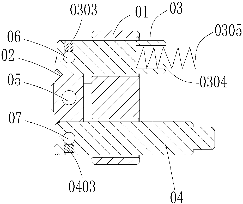
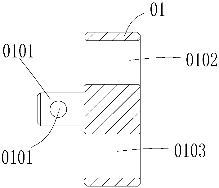
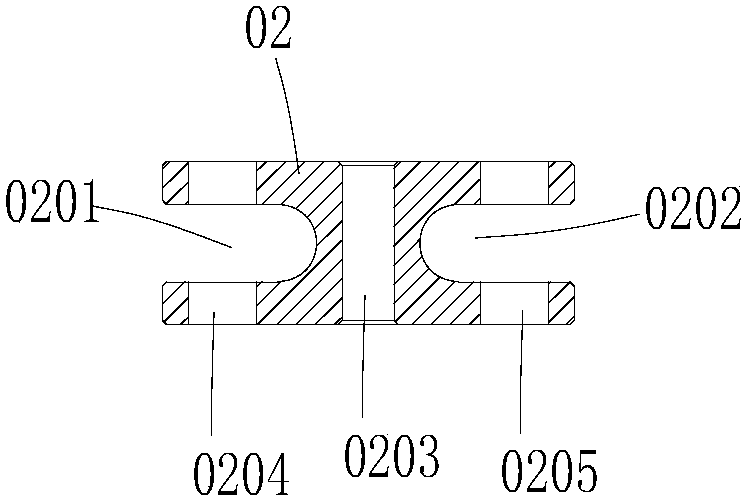
[0021] ginseng figure 1 , figure 2 and image 3 As shown, it includes a fixed seat 01, a connecting rod 02, a pressure rod 03 and a push rod 04. One end of the fixed seat 01 is provided with two bosses 0101, and the connecting rod 02 can be movably fixed between the two bosses 0101. The fixed seat 01 is provided with two The through holes are respectively the first through hole 0102 and the second through hole 0103. Two grooves are provided at both ends of t...


PUM


Abstract

The application discloses a self-lock device of a lower self-rotating mold. The self-lock device of the lower self-rotating mold comprises a fixed seat, a connecting rod, a pressure rod and an ejectorrod, wherein two lugs are arranged at one end of the fixed seat; the connecting rod is movably fixed between the two lugs; two through holes which are separately a first through hole and a second through hole are formed in the fixed seat; two grooves which are a first groove and a second groove are formed in two ends of the connecting rod; the pressure rod penetrates through the first through andis movably fixed to the first groove; and the ejector rod penetrates through the second through hole and is movably fixed to the second groove. The self-lock device disclosed by the invention is simple in structure, simple to draw materials and easy to process, and the lower self-rotating mold rotating to a processing station is prevented from being connected to a transmission gear box when the lower self-rotating mold and the transmission gear box are separated.

Description

technical field [0001] The present application relates to the field of turret punch presses, in particular to a self-locking device for a lower self-rotating die. Background technique [0002] The turret punching machine is a pressure processing equipment that uses a punch stamping die to perform punching processing and shallow drawing on the sheet. During the stamping process, the punch continuously hits the die to process the sheet. The sheet needs to be reset after the die is pressed down. Move to the next position that needs to be processed, and there is an autorotation mold station on the turret punching machine, and the mold needs to rotate during the processing, so the transmission gear box of the autorotation mold needs to mesh with the autorotation mold gear bayonet when the autorotation mold station is located. The transmission gearbox of the autorotation mold needs to be disengaged from the gear bayonet of the autorotation mold when it is not in the autorotation m...

Claims


Application Information

Patent Timeline
Patent Type & Authority Applications(China)
IPC IPC(8): B21D37/00B30B15/12
CPCB21D37/00B30B15/12
Inventor 徐涌涛
Owner 徐涌涛
Why Eureka
Try Eureka