Detection equipment calibration table

A technology of testing equipment and calibration table, applied in the direction of instruments, can solve the problems of low work efficiency, time-consuming and laborious, difficult operation, etc., and achieve the effect of reducing the difficulty of disassembly and replacement, optimizing the structure of the bent frame, and increasing the strength of the structure

Pending Publication Date: 2020-04-17
CHINA RAILWAY CONSTR HEAVY IND
View PDF7 Cites 0 Cited by
  • Summary
  • Abstract
  • Description
  • Claims
  • Application Information

AI Technical Summary

Problems solved by technology

However, the existing method is to perform rough zero calibration on a relatively standard maglev rail row without gain

Method used


Image

  • Detection equipment calibration table
  • Detection equipment calibration table
  • Detection equipment calibration table

Examples


Embodiment Construction

[0036] In order to understand the above-mentioned purpose, features and advantages of the present invention more clearly, the present invention will be further described in detail below in conjunction with the accompanying drawings and specific embodiments. It should be noted that, in the case of no conflict, the embodiments of the present invention and the features in the embodiments can be combined with each other.

[0037] In the following description, many specific details are set forth in order to fully understand the present invention. However, the present invention can also be implemented in other ways different from those described here. Therefore, the protection scope of the present invention is not limited by the specific details disclosed below. EXAMPLE LIMITATIONS.

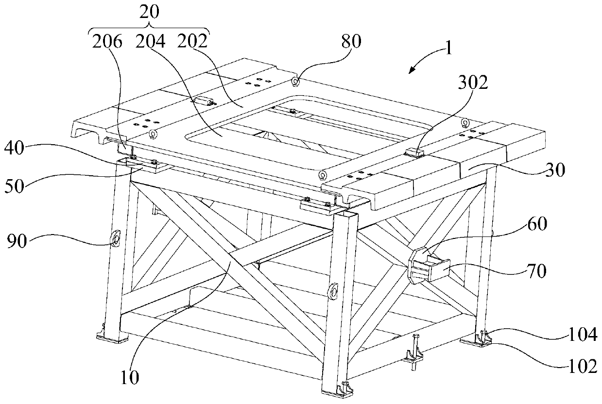
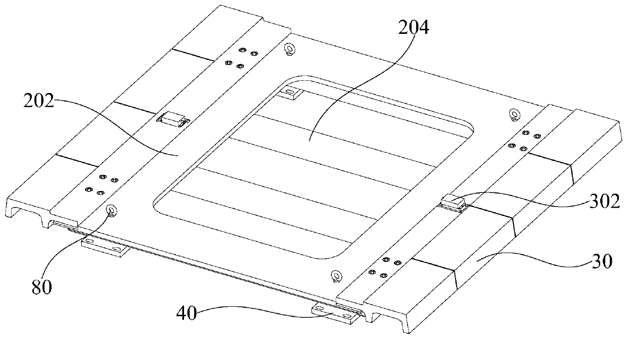
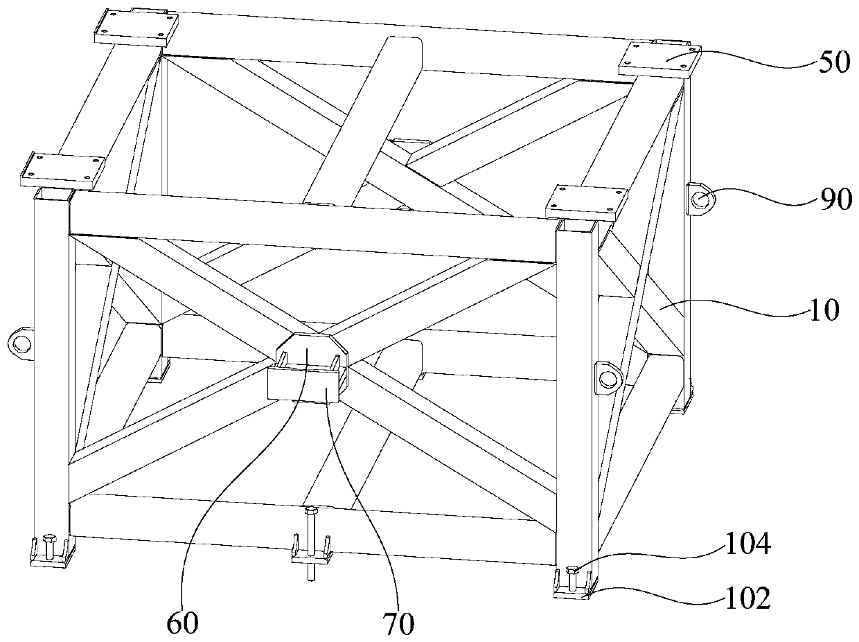
[0038] Refer below Figure 1 to Figure 4 The detection equipment calibration station 1 according to some embodiments of the present invention is described.

[0039] In view of this, according to the ...


PUM


Abstract

The invention provides a detection equipment calibration table. The detection equipment calibration table comprises a supporting frame; a bent frame which is detachably connected with the supporting frame; and a calibration track which is arranged on the bent frame. The detection equipment calibration table can provide a scene suitable for zero calibration and gain calibration for detection equipment, and migrates the calibration and calibration process to any scene from a solid track, thereby improving the operability of a user, reducing the difficulty of zero calibration and gain calibration, and improving the efficiency of zero calibration and gain calibration. Secondly, the bent frame is detachably connected with the supporting frame; the user can finish the procedure by detaching andreplacing the bent frame when calibration tracks of different models need to be replaced; therefore, the application range and practicability of the detection equipment calibration table are broadened, and the technical effects of optimizing the structure of the detection equipment calibration table, reducing the zero calibration and gain calibration difficulty of the detection equipment, improving the zero calibration and gain calibration efficiency of the detection equipment and improving the use experience of the user are achieved.

Description

technical field [0001] The invention relates to the technical field of magnetic levitation track detection, in particular to a detection equipment calibration platform. Background technique [0002] The stability, safety and passenger comfort of medium and low-speed maglev trains are closely related to the state of the maglev line, and regular inspection and maintenance are required. At present, there are many types of track inspection instruments or inspection trolleys for inspection and maintenance. Since the detection indicators such as maglev F rail and power supply rail require the corresponding rail inspection instrument or inspection car to have high detection accuracy, this determines that the calibration accuracy of the rail inspection instrument or inspection car is higher. However, the existing method is to perform rough zero calibration on a relatively standard maglev rail row without gain calibration, which has the problems of difficult operation, time-consumin...

Claims


Application Information

Patent Timeline
IPC IPC(8): G01D18/00
CPCG01D18/00
Inventor 罗建利黄超生杨峰江南志彭章硕左卓黄始强廖明璋刘为李新泉邵云
Owner CHINA RAILWAY CONSTR HEAVY IND
Why Eureka
Try Eureka