Optical fiber detection device
An optical fiber detection and tensioning device technology, applied in measurement devices, optical instrument testing, optical performance testing and other directions, can solve the problems of uneven winding, single function, inconvenient use, etc., and achieve the effect of novel conception and ingenious structure
- Summary
- Abstract
- Description
- Claims
- Application Information
AI Technical Summary
Problems solved by technology
Method used
Image

Examples
Embodiment Construction
[0019] The specific implementation manners of the present invention will be described in further detail below in conjunction with the accompanying drawings.
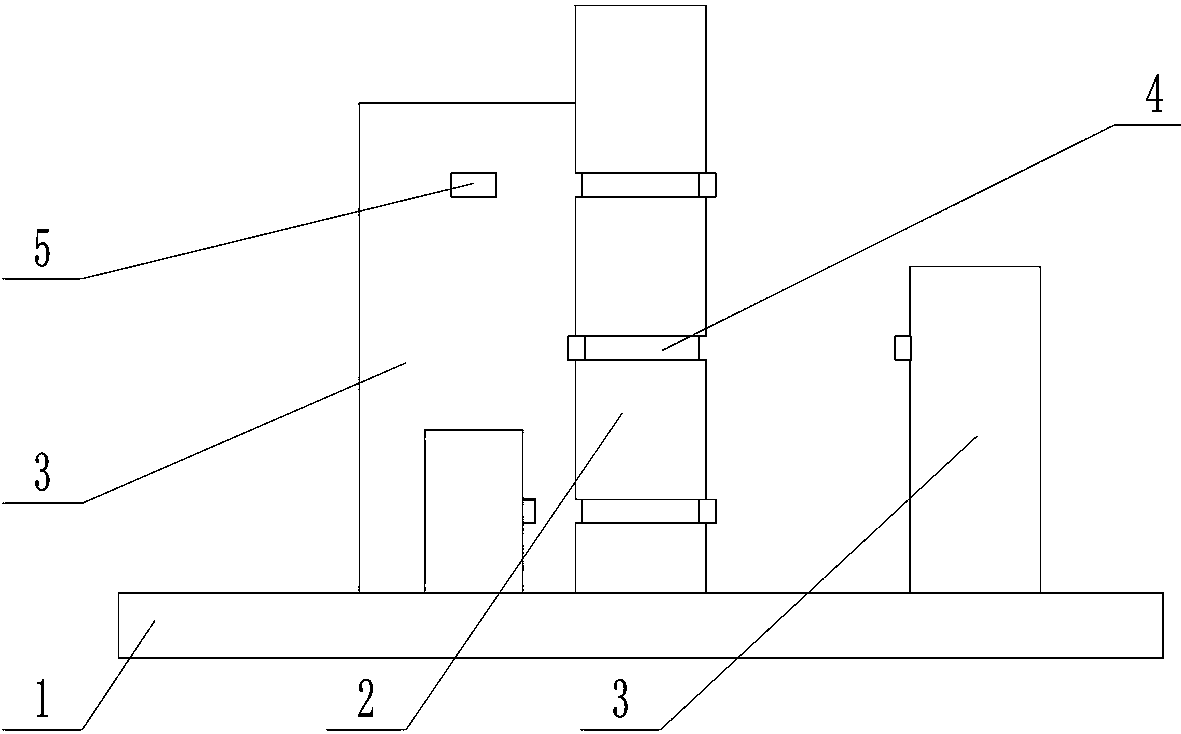
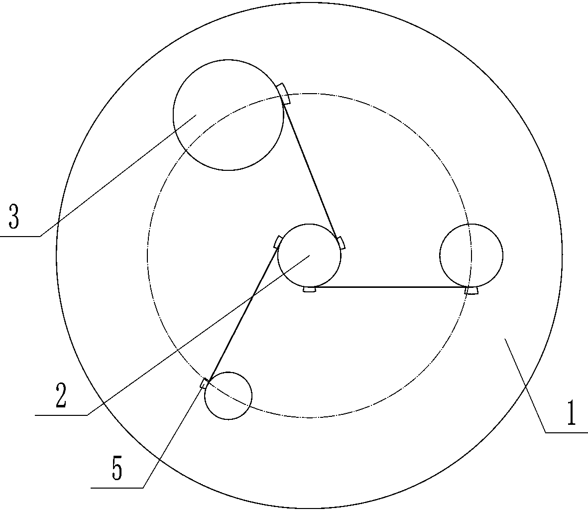
[0020] Depend on Figure 1-10 It can be seen that the present invention includes a disc-shaped base 1 placed horizontally, the center of the upper end surface of the base 1 is provided with a vertically placed fixed column 2, and the upper end surface of the base 1 is provided with a plurality of winding columns placed outside the fixed column 2 3. Each winding column 3 can rotate in one direction on the base 1. Multiple winding columns 3 are evenly distributed around the fixed column 2 and have different thicknesses. The height of the fixed column 2 is higher than that of the winding column 3 , the outer circular surface of the fixed column 2 is provided with a plurality of annular grooves 4, and the plurality of annular grooves 4 are evenly distributed up and down on the outer surface of the fixed column 2, and the num...
PUM
 Abstract
Description
Claims
Application Information
 - Generate Ideas
- Intellectual Property
- Life Sciences
- Materials
- Tech Scout
- Unparalleled Data Quality
- Higher Quality Content
- 60% Fewer Hallucinations
Browse by: Latest US Patents, China's latest patents, Technical Efficacy Thesaurus, Application Domain, Technology Topic, Popular Technical Reports.
© 2025 PatSnap. All rights reserved.Legal|Privacy policy|Modern Slavery Act Transparency Statement|Sitemap|About US| Contact US: help@patsnap.com