
An anti-loosening rail clamp

A rail presser and anti-loosening technology, which is applied in the direction of rail system, load hanging components, transportation and packaging, etc., can solve the problems of high labor intensity, increased vibration of the upper cover, and high danger in the operation process, and can achieve the Convenience and simple structure

Active Publication Date: 2019-08-13
CHINA MCC 2 GRP CO LTD
View PDF7 Cites 0 Cited by
  • Summary
  • Abstract
  • Description
  • Claims
  • Application Information

AI Technical Summary

Problems solved by technology

In practical applications, due to the vibration generated by the crane during the walking process, the pins will slowly withdraw from the base, and because the upper cover plate loses the positioning restriction function of the pins, the vibration of the upper cover plate will increase, resulting in The lock nut is loose and cannot achieve the purpose of better pressing the track
Due to the large number of rail clamps, the regular fastening of the workpieces of the rail clamps is extremely cumbersome and the operation process is dangerous and labor-intensive

Method used


Image

  • An anti-loosening rail clamp
  • An anti-loosening rail clamp
  • An anti-loosening rail clamp

Examples


Embodiment 1

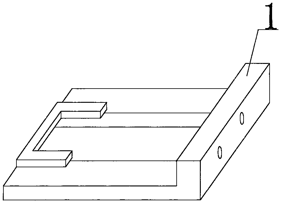
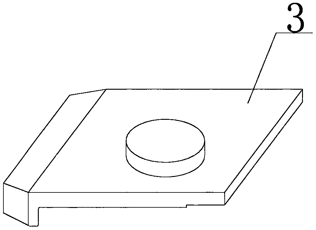
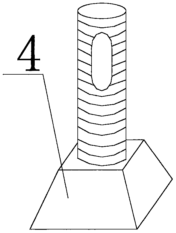
[0020] Embodiment one: see figure 1 , figure 2 , image 3 , Figure 4 , Figure 5 , Figure 6 , Figure 7 , the present invention relates to an anti-loosening rail clamp, comprising a base 1, a pin 2, an upper cover plate 3, a T-shaped bolt 4, a spring washer 8, a flat washer 7 and a lock nut 6, characterized in that it also includes a pin 5 and spacer 9, the pin 5 is processed by steel wire; two bolt holes are drilled in the middle of the outer edge of the base 1 and a screw thread is tapped in the drilled bolt hole, and a screw thread is connected to the drilled bolt hole. Bolt 10; the upper part of the T-shaped bolt 4 has an oval or circular through hole, and the pin 5 passes through the oval or circular through hole on the T-shaped bolt 4 and bends the two ends of the pin 5; The position of the oval or circular through hole on the upper part of the T-bolt 4 should ensure that after the lock nut 6 is tightened, the installed pin 5 is located at 1 to 2 mm above the lo...


PUM


Abstract

The invention relates to an anti-loosening rail clamp, which includes a base, a pin, an upper cover plate, a T-shaped bolt, a spring washer, a flat washer and a lock nut, and is characterized in that it also includes a pin and a spacer, and the pin is composed of It is made of steel wire; two bolt holes are drilled in the middle of the outer edge of the base, and a screw thread is tapped in the drilled bolt holes, and bolts are connected to the drilled bolt holes; the upper part of the T-shaped bolt is opened with an oval or circular through holes; the position of the oval or circular through holes on the upper part of the T-bolts should ensure that after the lock nuts are tightened, the installed pins are located at 1-2 mm above the lock nuts; the pads Installed between the base and the pin, the side of the pin in contact with the pin is processed into a saw shape; the side of the pin in contact with the pad is processed into a saw shape. The anti-loosening rail clamp can effectively prevent the threading pin from withdrawing from the base due to vibration and the lock nut can not be loosened due to vibration to achieve better compression of the rail, which solves the problem of regular tightening of the rail clamp.

Description

[0001] 1. Technical field: [0002] The invention relates to an anti-loosening rail clamp, which belongs to the technical field of crane rail fixing devices. [0003] 2. Background technology [0004] In the prior art, the rail clamp used to fix the rail of the crane beam usually includes a base, a pin, an upper cover plate, a T-bolt, a spring washer, a flat washer and a lock nut. The base is welded and fixed on the crane beam, and the pins are inserted into the base, and the lock nut on the upper cover is tightened after the gauge is adjusted to pass. In practical applications, due to the vibration generated by the crane during the walking process, the pins will slowly withdraw from the base, and because the upper cover plate loses the positioning restriction function of the pins, the vibration of the upper cover plate will increase, resulting in The looseness of the lock nut cannot achieve the purpose of better pressing the track. Due to the large number of rail clamps, the...

Claims


Application Information

Patent Timeline
Patent Type & Authority Patents(China)
IPC IPC(8): B66C7/08
CPCB66C7/08
Inventor 贾成一
Owner CHINA MCC 2 GRP CO LTD
Learn More