Spinning melt filtering apparatus

A filter device and melt technology, applied in the direction of spinning solution degassing, etc., can solve the problems of damage to the filter screen, affect melt filtration, jamming, etc., achieve simplified structure, high replacement efficiency, and guarantee convenience Effect

Active Publication Date: 2018-06-01
CHANGSHU GOLD SPRING CHEM FIBERS & KNITTINGS
View PDF14 Cites 3 Cited by
  • Summary
  • Abstract
  • Description
  • Claims
  • Application Information

AI Technical Summary

Problems solved by technology

This patent application scheme has the following shortcomings: one, due to the need to open a filter chamber for setting the filter screen on the piston rod, thereby increasing the structural complexity of the entire hydraulic mechanism; Once the aforementioned filter mesh cavity on the piston rod is difficult to obtain the matching effect with the filter mesh due to factors such as wear and tear, the filter mesh will become loose or deformed, which will affect the filtration of the melt, and even cause the filter mesh to come out. The filter cavity is stuck at the inlet and outlet channels of the melt, which increases the difficulty of inspection; third, because the filter is detachable and snapped into the filter cavity on the piston rod, it can be taken out and cleaned. The filter must be driven out of the filter cavity with the help of corresponding tools, and there is a risk of damaging the filter with tools

Method used


Image

  • Spinning melt filtering apparatus
  • Spinning melt filtering apparatus
  • Spinning melt filtering apparatus

Examples


Embodiment Construction

[0026] In order to understand the technical essence and beneficial effects of the present invention more clearly, the applicant will describe in detail the following in the form of examples, but the description of the examples is not to limit the solution of the present invention. Equivalent transformations that are only formal but not substantive should be regarded as the scope of the technical solution of the present invention.

[0027] In the following descriptions, all concepts related to directionality or orientation of up, down, left, right, front and rear are based on figure 1 The shown position status is a reference, so it cannot be understood as a special limitation on the technical solution provided by the present invention.

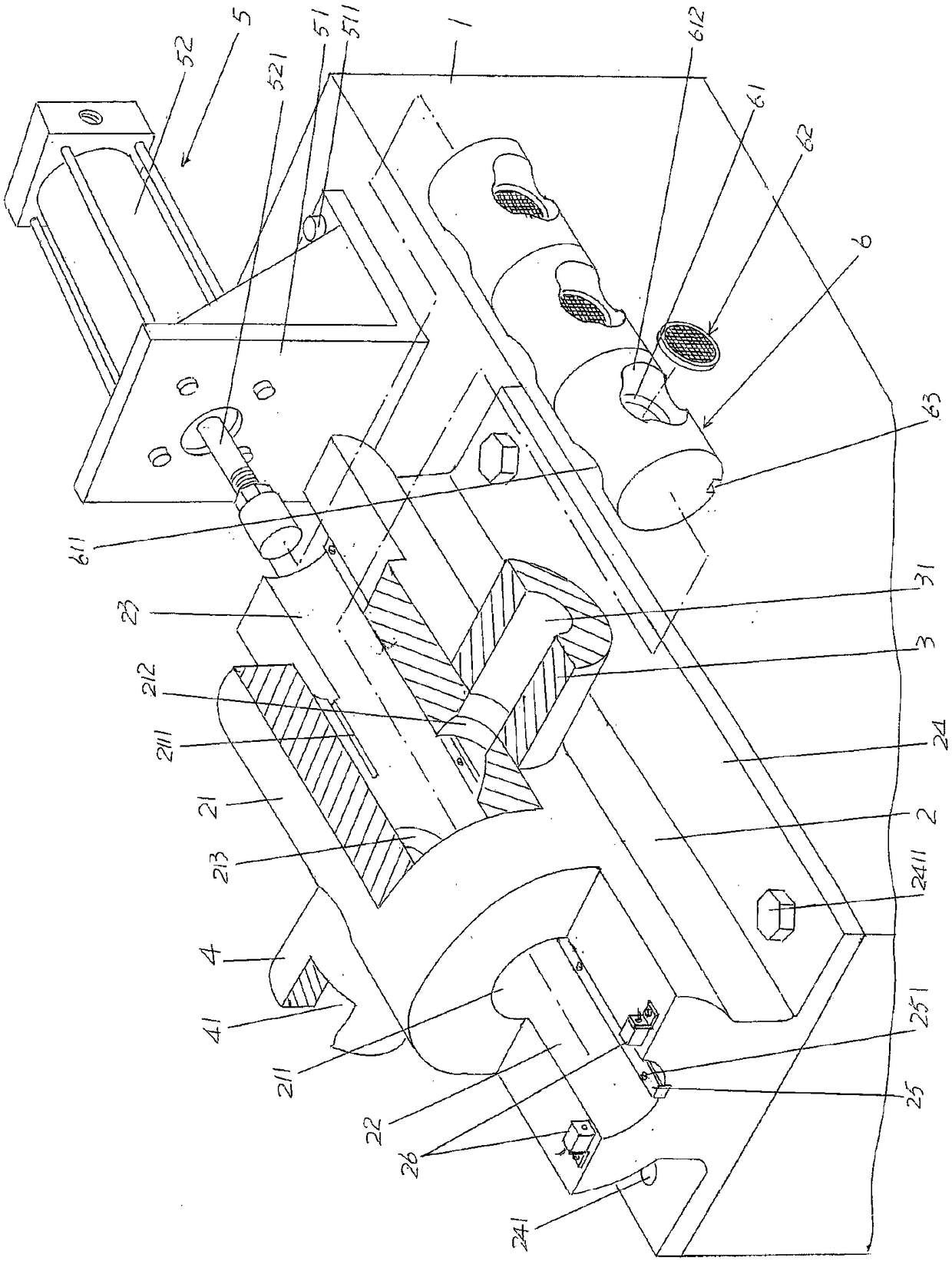
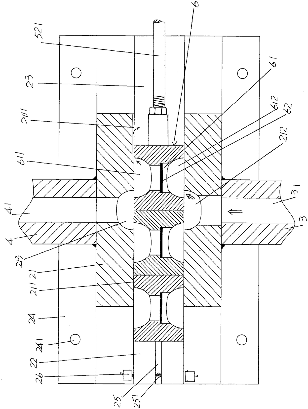
[0028] See figure 1 and image 3, shows a base 1; shows a filter cartridge seat 2, the filter cartridge seat 2 is fixed on the upper part of the aforementioned base 1, on the upper part of the filter cartridge seat 2 and in the length directi...


PUM


Abstract

The invention relates to a spinning melt filtering apparatus. The spinning melt filtering apparatus comprises a foundation support, a filtering cylinder holder, a melt inlet, a melt outlet, a hydraulic mechanism and a filtering module, wherein the filtering cylinder holder is fixed on the upper portion of the foundation support, the upper portion of the filtering cylinder holder is provided with afiltering cylinder, the front upper portion of the filtering cylinder holder is provided with a filtering module cavity to be cleaned, and the rear upper portion is provided with a filtering module cavity to be used; the melt inlet and the melt outlet correspond to each other in the lateral direction and are respectively connected with the filtering cylinder; the hydraulic mechanism is fixed on the foundation support at the position corresponding to the rear end of the filter cylinder holder; the filtering module is arranged in the filtering cylinder cavity and corresponds to a position between the melt inlet and the melt outlet, the middle portion of the filtering module is provided with a filtering net seat cavity, a filtering net is arranged in the filtering net seat cavity, when the filtering net is blocked to change the filtering module to the filtering module to be cleaned, the filtering module stored in the filtering module cavity to be used is pushed to the filtering cylindercavity under the action of the hydraulic mechanism so as to replace the filtering module to be cleaned, and the filtering module to be cleaned enters the cleaning filtering module cavity. By adoptingthe spinning melt filtering apparatus, the structure of the hydraulic mechanism is simplified; the filtering module replacement efficiency is high; and the convenience in maintenance and cleaning canbe realized.

Description

technical field [0001] The invention belongs to the technical field of melt spinning equipment, and in particular relates to a spinning melt filtering device. Background technique [0002] As known in the industry, to produce polyester fibers by melt spinning, a filter device needs to be set at a position corresponding to the melt output end of the screw extruder, that is, the melt extrusion end, and usually two filter devices are used, and each filter device has a filter. When there are many impurities attached to the filter screen of the filter device, it will affect the normal filtration of the melt. Due to the use of two filter devices, the uninterrupted filtration of the melt can be ensured by switching. For example, when the aforementioned filter screen on one filter device is severely blocked by impurities and cleaning is carried out, the other filter that is on standby The filter unit takes over so that the filtration of the melt is not interrupted during the cleani...

Claims


Application Information

Patent Timeline
Patent Type & Authority Applications(China)
IPC IPC(8): D01D1/10
CPCD01D1/106Y02P70/62
Inventor 符敏初杨新华李文俊王维平
Owner CHANGSHU GOLD SPRING CHEM FIBERS & KNITTINGS
Why Eureka
Try Eureka