Mechanical-hydraulic double-acting release rotary tail pipe hanger

A liner hanger, double-acting technology, used in wellbore/well components, sealing/packaging, earth-moving drilling, etc. Well quality and the effect of improving displacement efficiency

Inactive Publication Date: 2013-09-04
CHINA NAT PETROLEUM CORP CHUANQING DRILLING ENG CO LTD
View PDF6 Cites 18 Cited by
  • Summary
  • Abstract
  • Description
  • Claims
  • Application Information

AI Technical Summary

Problems solved by technology

Therefore, the on-site construction risk of the hanger is relatively high

Method used


Image

  • Mechanical-hydraulic double-acting release rotary tail pipe hanger
  • Mechanical-hydraulic double-acting release rotary tail pipe hanger
  • Mechanical-hydraulic double-acting release rotary tail pipe hanger

Examples


Embodiment 1

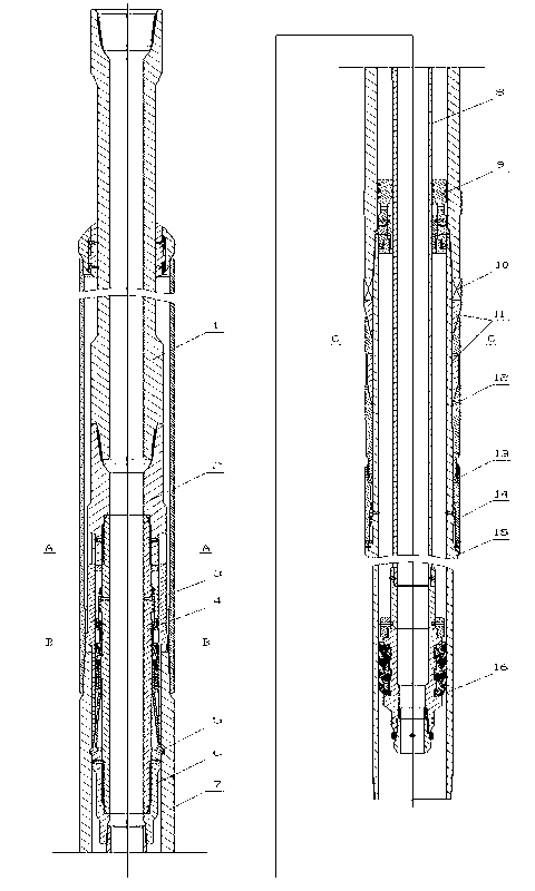
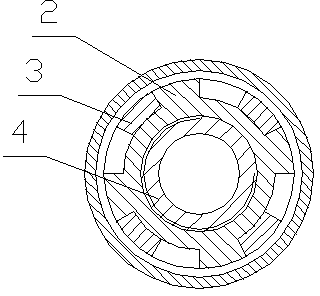
[0038] As a preferred embodiment of the present invention, the present invention mainly includes a short drill pipe 1, an upper joint 2, a torque cylinder 3, a double male joint 4, a claw block 5, a lower joint 6, a male and female joint 7, and a hand-discharging mechanism , sealing box 9, hollow rubber plug 16 and carrying mechanism. Wherein, the airtight box and the hand-losing mechanism can adopt the airtight box and the hand-losing mechanism in the prior art.

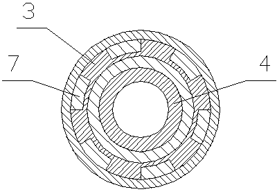
[0039] The upper joint 2 is engaged with the meshing teeth on the upper end of the torque cylinder 3 through the spline shaft, and the torque cylinder 3 is engaged with the meshing teeth on the upper end of the male and female joints 7 through the spline shaft, and the claw block 5 is fitted through the lower joint 6 The support is stuck in the inner groove of the male and female joints 7, and the sitting and hanging liquid cylinder 14, light-load bearing 13, conjoined double slips 12, conjoined double-cone 11, and he...

Embodiment 2

[0043] As the best embodiment of the present invention: the present invention mainly includes a short drill pipe 1, an upper joint 2, a torque cylinder 3, a double male joint 4, a claw block 5, a lower joint 6, a male and female joint 7, and a heavy-duty bearing 10. Conjoined double cone 11, conjoined double slips 12, sitting and hanging liquid cylinder 14, center pipe 15 and hollow rubber plug 16. The upper end of the short drill pipe 1 is provided with a drill pipe female thread to realize the connection with the drill pipe, and the lower end of the hanger is provided with a casing male thread to realize the connection with the liner. The claw block 5 is supported and stuck in the inner groove of the male and female joints 7 through the tapered surface support on the upper end of the lower joint 6, so as to realize carrying the tail pipe. The spline shaft on the upper joint 2 engages with the meshing teeth provided on the upper end of the torque cylinder 3, and the spline sh...

Embodiment 3

[0048] In yet another embodiment of the present invention, the hands-free cylinder 18 is arranged on the double male joint 4, and a cavity is left on the upper part, and the claw 21 is connected to the hands-free cylinder 18 through a connection mechanism and a hands-free control pin 19. The lower part of the elastic claw 21 is provided with an outward elastic claw block 5, and the elastic claw block 5 is supported in the groove of the male and female joint 7 through the conical surface support at the upper end of the lower joint 6, and the upper joint 2 passes through the flower. The key shaft is engaged with the meshing teeth at the upper end of the torque cylinder 3, and the meshing teeth at the lower end of the torque cylinder 3 are engaged with the meshing teeth at the upper end of the male and female joints 7. The conjoined double cone 11 and the conjoined double slips 12 are inserted into the Fitted together, the sitting and hanging liquid cylinder 14, light-load bearing...


PUM


Abstract

The invention discloses a mechanical-hydraulic double-acting release rotary tail pipe hanger, and belongs to the technical field of manufacturing downhole tools for oil and gas well cementing operations in oil and gas development. The mechanical-hydraulic double-acting release rotary tail pipe hanger comprises a short drill pipe, an upper joint, a release mechanism, a double male joint, a male and female joint and a lower joint. The short drill pipe, the upper joint, the double male joint and the lower joint are connected in a threaded manner from up to down sequentially. The mechanical-hydraulic double-acting release rotary tail pipe hanger further comprises a loading mechanism comprising a hanger set hydraulic cylinder, a light-load bearing, conjoined twin slips, a conjoined twin cone, a heavy-duty bearing and a central pipe. The hanger set hydraulic cylinder, the light-duty bearing, the conjoined twin slips, the conjoined twin cone and the heavy-duty bearing are arranged on the central pipe from down to up sequentially. The central pipe is connected at the lower end of the male and female joint. The heavy-duty bearing is arranged between the male and female joint and the conjoined twin cone. By the aid of the mechanical-hydraulic double-acting release rotary tail pipe hanger, a tail pipe can rotate when the a tube pillar enters, after the hanger is set and is separated from a releasing release, the slips and the bearings bear the hanger, and functions of rotating and well cementing of a heavy-duty tail pipe is realized.

Description

[0001] technical field [0002] The invention relates to a mechanical-hydraulic double-action hands-free rotary liner hanger, which belongs to the technical field of downhole tool manufacturing for oil and gas well cementing operations in oil and gas development. Background technique [0003] When performing liner cementing in the drilling process of complex wells such as deep wells, ultra-deep wells, highly deviated wells, horizontal wells and low-pressure leakage wells, dredge and stabilize the well to ensure that the casing runs smoothly to the designed position However, a large amount of well drilling, observation and mud treatment are often required, and a large amount of drilling time and cost are required. Even through careful well preparation and careful casing running measures, sometimes the liner string encounters midway. The card is blocked and cannot be lowered to the designed position. During cementing construction, for deep and ultra-deep wells, the pipe strin...

Claims


Application Information

Patent Timeline
Patent Type & Authority Applications(China)
IPC IPC(8): E21B23/01E21B23/04E21B33/13
Inventor 唐欣李斌张毅超叶登胜
Owner CHINA NAT PETROLEUM CORP CHUANQING DRILLING ENG CO LTD
Why Eureka
Try Eureka