
Image processing device, image processing method, and program

a technology of image processing and image, applied in the field of image processing device, image processing method, and program, can solve the problem of difficulty for users to view the obtained superimposed image, and achieve the effect of facilitating the input of operation

Active Publication Date: 2013-11-07
SONY CORP
View PDF31 Cites 19 Cited by
  • Summary
  • Abstract
  • Description
  • Claims
  • Application Information

AI Technical Summary

Benefits of technology

This solution enhances user input efficiency by allowing users to interact with and select items in their environment directly through AR, improving the visibility and usability of superimposed information within the AR interface.

Problems solved by technology

When such a case occurred, there was an issue that it became difficult for a user to view a superimposed image obtained by superimposing the superimposition display data on the shot image.

Method used


Image

  • Image processing device, image processing method, and program
  • Image processing device, image processing method, and program
  • Image processing device, image processing method, and program

Examples


first embodiment

2. First Embodiment

[0070]FIG. 3 is a block diagram illustrating an example of a configuration of the image processing device 100 according to the first embodiment. With reference to FIG. 3, the image processing device 100 includes an imaging unit 102, an environment map generating unit 110, and an output image generating unit 180.

2-1. Imaging Unit

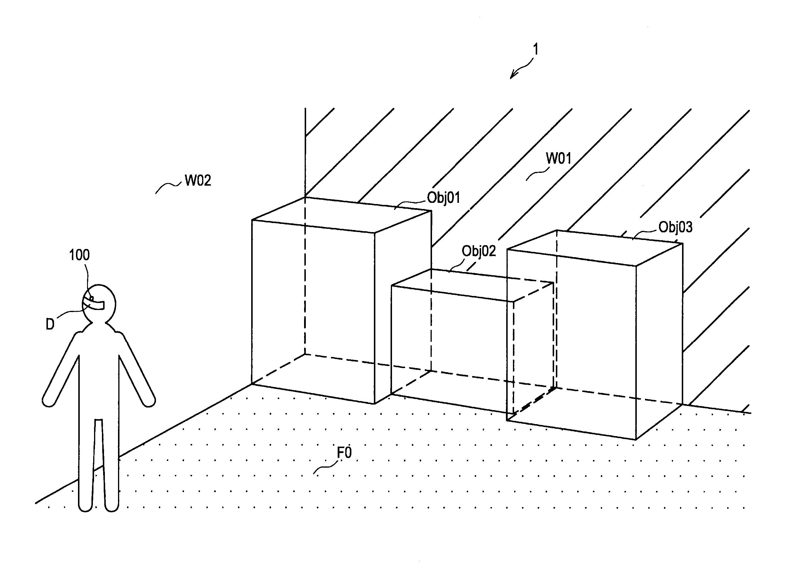
[0071]The imaging unit 102 may be realized as an imaging device having an imaging element such as a charge coupled device (CCD) or a complementary metal oxide semiconductor (CMOS), for example. Although the imaging unit 102 is composed as a part of the image processing device 100 in this embodiment, the imaging unit 102 may be provided outside the image processing device 100. The imaging unit 102 outputs an image generated by imaging the real space such as the environment 1 illustrated in FIG. 1 to the environment map generating unit 110 and the output image generating unit 180 as the input image.

2-2. Environment Map Generating Unit

[007...

second embodiment

3. Second Embodiment

[0154]In the first embodiment, an example in which the wall surface and the floor surface in the real space are also recognized as the objects is described. On the other hand, in the case where the feature data corresponding to the wall surface or the floor surface is not defined in advance, the wall surface or the floor surface is not included in the environment map. In this case, it is preferable to additionally recognize the wall surface or the floor surface to generate the output image according to a recognition result. Therefore, in this section, an example of the configuration of the image processing device capable of additionally recognizing the wall surface or the floor surface when the wall surface or the floor surface is not included in the environment map is described as a second embodiment of the present invention.

[0155]FIG. 14 is a block diagram illustrating an example of a configuration of an image processing device 200 according to the second embod...


PUM


Abstract

There is provided an image processing device including a superimposition display position determining unit which determines a position of an object having a predetermined flat surface or curved surface out of an object imaged in an input image based on an environment map, a superimposition display image generating unit which generates a superimposition display image by setting superimposition display data at the position of the object determined by the superimposition display position determining unit, an image superimposing unit which superimposes the superimposition display image on a visual field of a user, an operating object recognizing unit which recognizes an operating object imaged in the input image, and a process executing unit which executes a process corresponding to an item selected based on a position of the operating object recognized by the operating object recognizing unit.

Description

CROSS-REFERENCE TO RELATED APPLICATION[0001]This application is a continuation of U.S. application Ser. No. 13 / 049,433, filed Mar. 16, 2011, the entire contents of which are incorporated herein by reference, and claims priority to Japanese Application Nos. 2010-068269, filed Mar. 24, 2010 and 2010-068270, filed Mar. 24, 2010.BACKGROUND OF THE INVENTION[0002]1. Field of the Invention[0003]The present invention relates to an image processing device, an image processing method, and a program.[0004]2. Description of the Related Art[0005]Recently, technology referred to as augmented reality (AR) has been drawing attention whereby an image obtained by imaging a real space and modified through a specific process is presented to a user. In the AR technology, useful information on an object in a real space shown in an input image may be inserted into the image to be output as an output image, for example. That is, in the AR technology, typically, a large part of the image presented to the us...

Claims


Application Information

Patent Timeline
Patent Type & Authority Applications(United States)
IPC IPC(8): G06T19/00G06F3/033G06F3/0346G06F3/048H04N23/40
CPCG06T19/006G06F3/011G06T7/73G06T7/277G02B27/017G02B2027/0138G02B2027/0141G02B2027/0187G06F3/017G09G5/00G06F3/04842G02B27/0172G02B2027/014G06F3/012G06F3/0482
Inventor KASHITANI, TATSUKI
Owner SONY CORP
Learn More