Systems and methods for multiple aspirators for a constant pump rate

a technology of multiple aspirators and constant pump rate, which is applied in the direction of machine/engine, combustion air/fuel air treatment, charge feed system, etc., can solve the problems of increasing the cost of engine system components, affecting the performance of the engine, and affecting the efficiency of the engine, so as to achieve low-cost vacuum generation and save fuel and/or energy efficiency. , the effect of reducing the cost of production

Active Publication Date: 2015-02-12
FORD GLOBAL TECH LLC
View PDF3 Cites 14 Cited by
  • Summary
  • Abstract
  • Description
  • Claims
  • Application Information

AI Technical Summary

Benefits of technology

[0002]Vehicle engine systems may include various vacuum consumption devices that are actuated using vacuum. These may include, for example, a brake booster. Vacuum used by these devices may be provided by a dedicated vacuum pump, such as an electrically-driven or engine-driven vacuum pump. While such vacuum pumps advantageously produce a pumping curve that is independent of intake manifold pressure, they do so at the expense of fuel and/or energy efficiency. As an alternative to such resource-consuming vacuum pumps, one or more aspirators may be coupled in an engine system to harness engi

Problems solved by technology

While such vacuum pumps advantageously produce a pumping curve that is independent of intake manifold pressure, they do so at the expense of fuel and/or energy efficiency.
Whereas conventional vacuum pumps produce a pumping curve which is independent of intake manifold pressure, pumping curves for aspirators arrange

Method used


Image

  • Systems and methods for multiple aspirators for a constant pump rate
  • Systems and methods for multiple aspirators for a constant pump rate
  • Systems and methods for multiple aspirators for a constant pump rate

Examples


Embodiment Construction

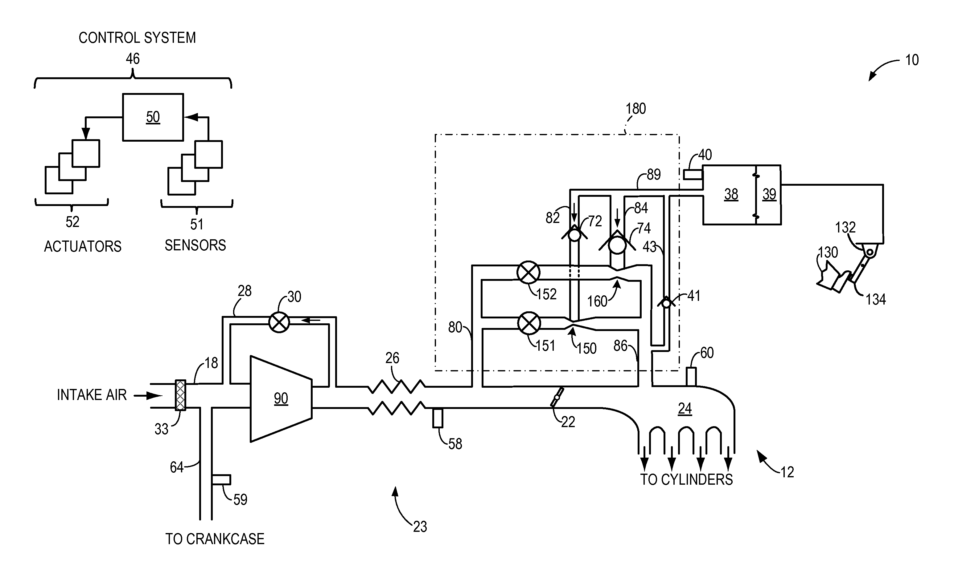
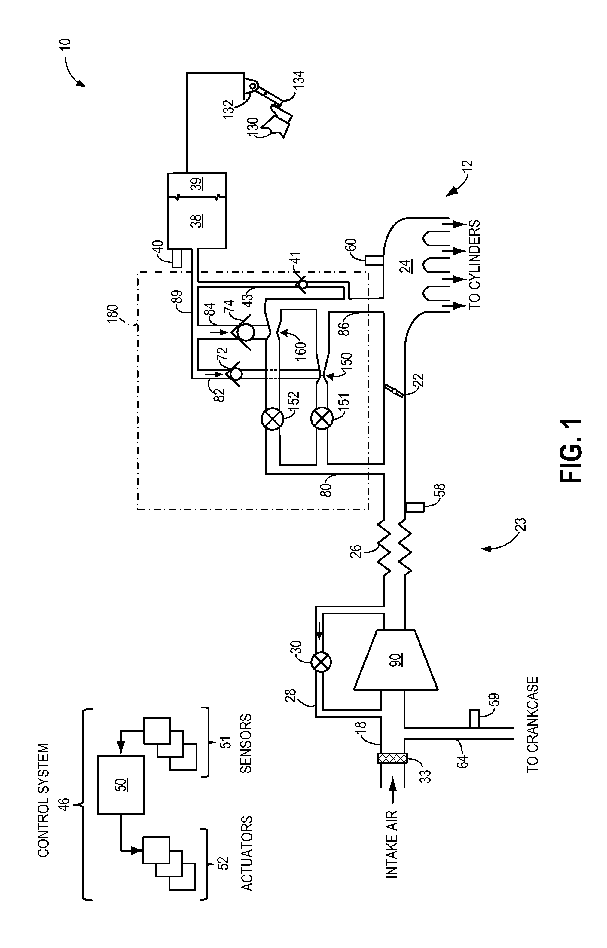
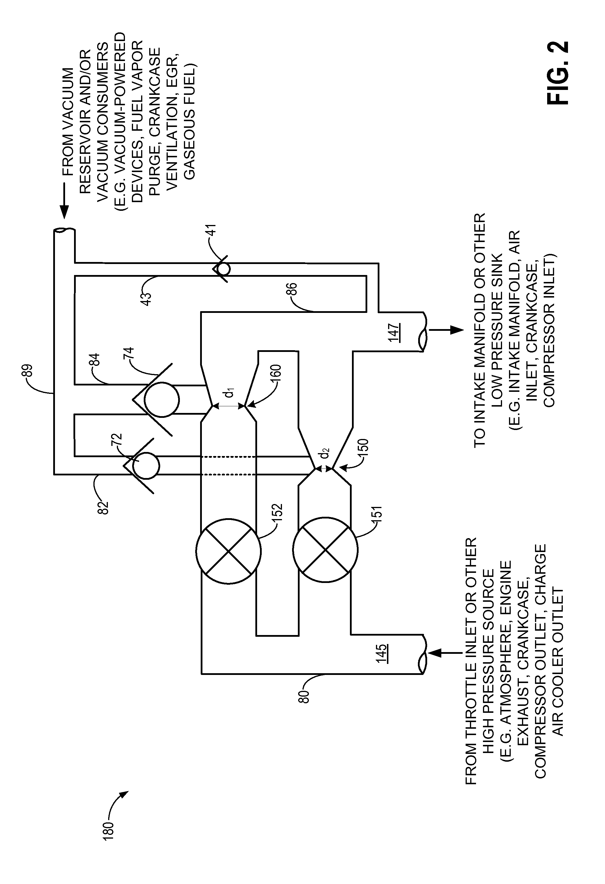
[0015]Methods and systems are provided for controlling a motive flow rate through a parallel arrangement of valved aspirators coupled to an engine system, such as the engine systems of FIG. 1. A detail view of an aspirator arrangement which may be included in the engine system of FIG. 1 is provided in FIG. 2. A combined motive flow rate through the aspirator arrangement may be adjusted via control of aspirator shut-off valves of the aspirator arrangement, for example as a function of intake manifold pressure. By adjusting the aspirator shut-off valves to increase motive flow through the aspirators as intake manifold pressure increases (e.g., as intake manifold vacuum decreases), and by directing some flow through the intake throttle when a desired engine air flow rate exceeds a maximum combined motive flow rate through the aspirator arrangement (FIGS. 4A-B), a desired engine air flow rate may be achieved over a range of intake manifold pressures and more vacuum may be generated at t...


PUM


Abstract

Methods and systems are provided for a parallel arrangement of at least two valved aspirators, with a high pressure source such as an intake throttle inlet coupled to a motive inlet of the arrangement and a low pressure sink such as an intake throttle outlet coupled to a mixed flow outlet of the arrangement. Intake throttle position and respective valves arranged in series with each aspirator of the arrangement are controlled based on intake manifold pressure and/or a desired engine air flow rate, for example such that a combined motive flow rate through the arrangement increases as intake manifold pressure increases. An intake throttle with a fully closed default position may be used in conjunction with the arrangement; during a fault condition where the intake throttle is fully closed, the valves of the arrangement may be controlled to achieve a controllable engine air flow rate during the fault condition.

Description

FIELD[0001]The present invention relates to a parallel arrangement of valved aspirators coupled to an engine system. A combined motive flow rate through the aspirators may be controlled to achieve a pumping performance comparable to that of a conventional electrically-driven or engine-driven vacuum pump.BACKGROUND AND SUMMARY[0002]Vehicle engine systems may include various vacuum consumption devices that are actuated using vacuum. These may include, for example, a brake booster. Vacuum used by these devices may be provided by a dedicated vacuum pump, such as an electrically-driven or engine-driven vacuum pump. While such vacuum pumps advantageously produce a pumping curve that is independent of intake manifold pressure, they do so at the expense of fuel and / or energy efficiency. As an alternative to such resource-consuming vacuum pumps, one or more aspirators may be coupled in an engine system to harness engine airflow for generation of vacuum. Aspirators (which may alternatively be...

Claims


Application Information

Patent Timeline
IPC IPC(8): F02M35/10
CPCF02M35/10118F02M35/10229F02M35/10255F02M35/10386F02D9/02F02D2009/022F02D2009/0235F02D2009/0279
Inventor PURSIFULL, ROSS DYKSTRA
Owner FORD GLOBAL TECH LLC
Why Eureka
Try Eureka