Method of controlling aspirator motive flow

Active Publication Date: 2016-08-04
FORD GLOBAL TECH LLC
View PDF18 Cites 6 Cited by
  • Summary
  • Abstract
  • Description
  • Claims
  • Application Information

AI Technical Summary

Benefits of technology

[0008]In this way, ACV operation may be controlled for vacuum generation. Controlling the motive flow rate through the aspirator based on engine speed provides a more simplified control of the ACV. Further, by modulating the ACV based on engine speed, aspirator and ACV operation may be tested

Problems solved by technology

For example, opening the ASOV for vacuum generation during certain engine conditions may adversely affect emissions.
Further, by controlling the ASOV based

Method used


Image

  • Method of controlling aspirator motive flow
  • Method of controlling aspirator motive flow
  • Method of controlling aspirator motive flow

Examples


Embodiment Construction

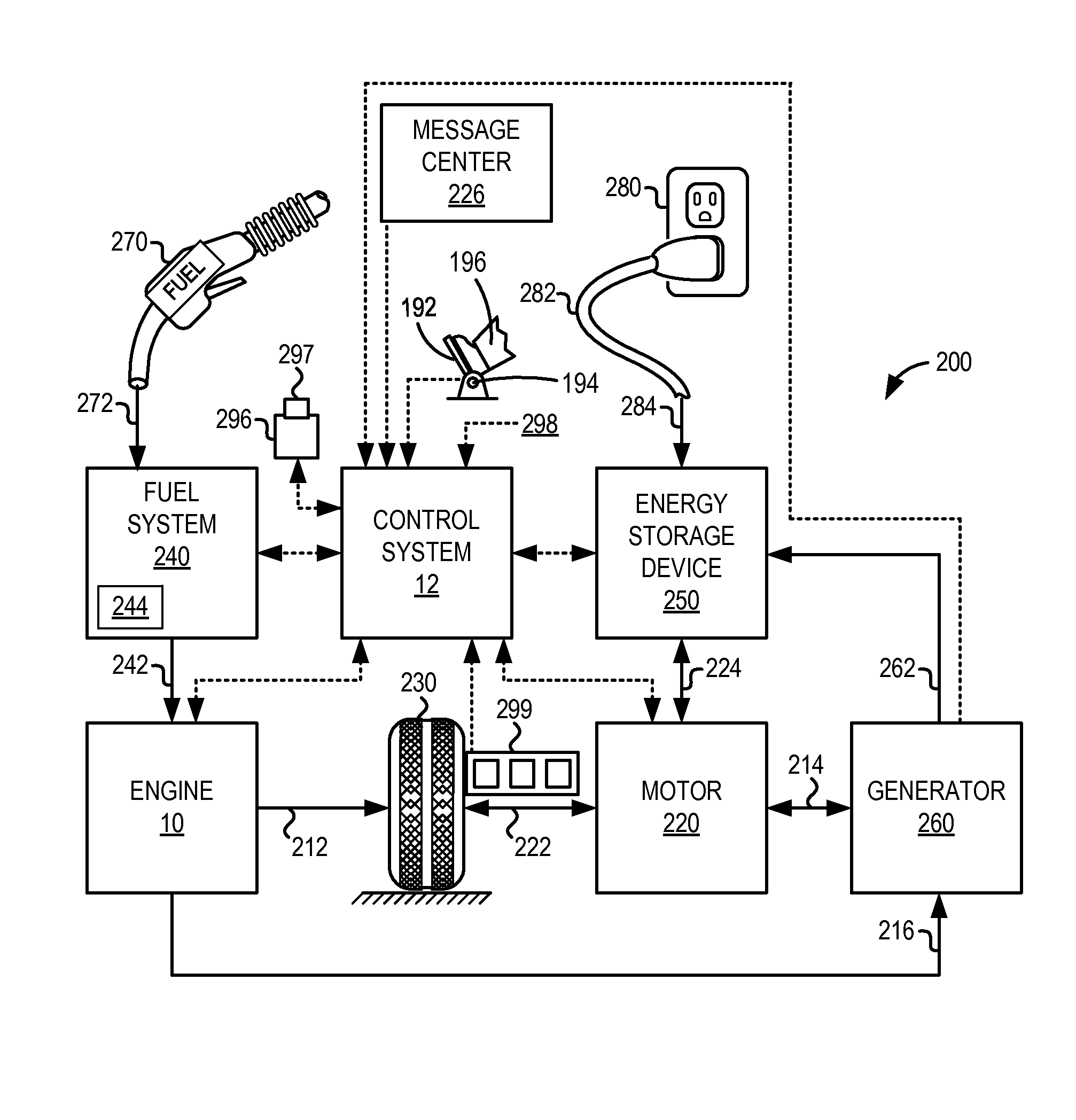
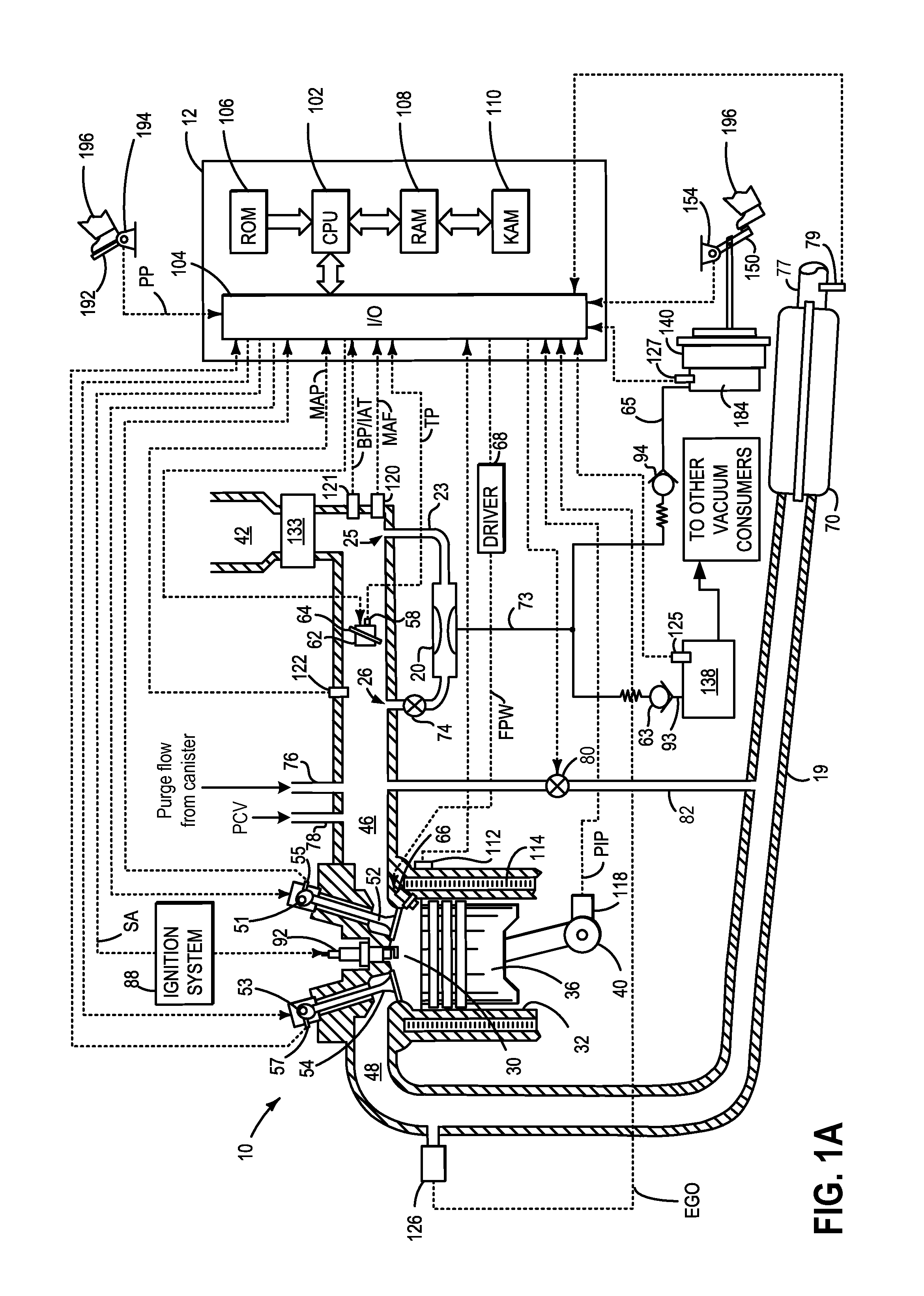
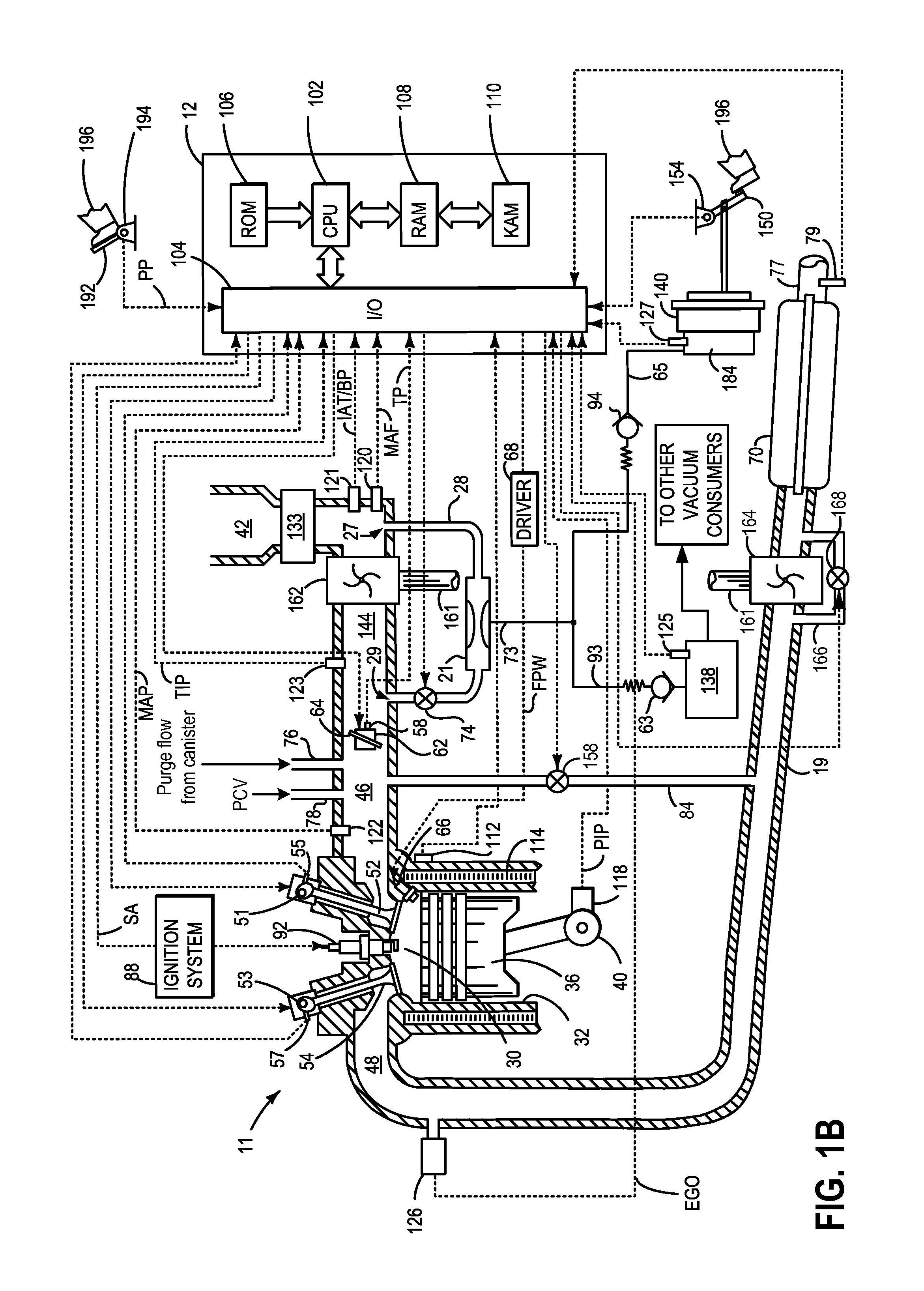
[0025]The following detailed description relates to methods and systems for generating vacuum at an aspirator coupled to an engine system, such as the naturally aspirated engine system of FIG. 1A and the forced induction engine system of FIG. 1B. The engine system may be included in a hybrid electric vehicle (HEV), such as the hybrid vehicle system shown in FIG. 2. Vacuum generation at the aspirator may be regulated by an aspirator shut-off valve (ASOV) coupled either upstream or downstream of the aspirator. As such, an opening of the ASOV may be adjusted to control motive flow through the aspirator, thus, controlling an amount of vacuum generated at the aspirator. A controller may be configured to perform one or more control routines, such as the example routines of FIGS. 3-10B, to open or close the ASOV based on engine conditions (FIGS. 3 and 4) such as engine speed (FIG. 6), a temperature of the ASOV (FIG. 8) which may depend on a current and voltage provided to the ASOV (FIG. 9)...


PUM


Abstract

Methods and systems are provided for controlling an aspirator shut-off valve in a boosted engine. One example method includes increasing an opening of the aspirator shut-off valve to allow motive flow through an aspirator in response to engine speed between a first, lower speed and a second, higher speed. As such, control of the aspirator shut-off valve may be simplified.

Description

FIELD[0001]The present invention relates to controlling motive flow through an ejector coupled to an engine system.BACKGROUND AND SUMMARY[0002]Vehicle systems may include various vacuum consumption devices that are actuated using vacuum. These may include, for example, a brake booster, a fuel vapor canister etc. Vacuum used by these devices may be provided by a dedicated vacuum pump. In still other embodiments, one or more aspirators (alternatively referred to as ejectors, venturi pumps, jet pumps, and eductors) may be coupled in the engine system that may harness engine air flow and use it to generate vacuum.[0003]Since aspirators are passive devices, they provide low-cost vacuum generation when utilized in engine systems. An amount of vacuum generated at an aspirator can be controlled by controlling the motive air flow rate through the aspirator. While aspirators may generate vacuum at a lower cost and with improved efficiency as compared to electrically-driven or engine-driven va...

Claims


Application Information

Patent Timeline
IPC IPC(8): F02M35/10
CPCF02M35/10157F02M35/10229F02D9/02F02M35/10B60T13/46B60T17/02B60T17/04
Inventor LUEHRSEN, ERICPURSIFULL, ROSS DYKSTRA
Owner FORD GLOBAL TECH LLC
Why Eureka
Try Eureka