Method of controlling aspirator motive flow

a technology of motive flow and aspirator, which is applied in the direction of electric control, combustion air/fuel air treatment, braking system, etc., can solve the problems of engine shutdown events that can produce degraded noise, vibration and harshness (nvh), and engine shutdown shake, so as to improve fuel economy

Active Publication Date: 2016-09-22
FORD GLOBAL TECH LLC
View PDF2 Cites 6 Cited by
  • Summary
  • Abstract
  • Description
  • Claims
  • Application Information

AI Technical Summary

Benefits of technology

[0004]Since aspirators are passive devices, they provide low-cost vacuum generation when utilized in engine systems. An amount of vacuum generated at an aspirator can be controlled by controlling the motive air flow rate through the aspirator. While aspirators may generate vacuum at a lower cost and with improved efficiency as compared to electrically-driven or engine-driven vacuum pumps, their use in engine intake systems has traditionally been constrained by both available intake manifold vacuum and maximum throttle bypass flow. Some approaches for addressing this issue involve arranging a valve in series with an aspirator, or incorporating a valve into the structure of an aspirator. Such valves may be referred to as aspirator shut-off valves (ASOVs) or aspirator control valves (ACVs). An opening amount of the valve is regulated to control the motive air flow rate through the aspirator, and thereby control an amount of vacuum generated at the aspirator. By controlling the opening amount of the valve, the amount of air flowing through the aspirator and the suction air flow rate can be varied, thereby adjusting vacuum generation as engine operating conditions such as intake manifold pressure change.
[0007]The above issues may be addressed by a method of operating a hybrid vehicle system, comprising, following a shut-down command to an engine, opening an aspirator control valve (ACV) between a first engine speed and a second engine speed, the first engine speed being lower than an idle speed and the second engine speed occurring immediately before an imminent engine stop. In this way, NVH issues due to engine shutdown shake may be reduced.
[0010]In this way, additional vacuum may be generated and stored in a vacuum reservoir for future use by opening the ASOV as engine rotation slows down subsequent to an engine-off command in a HEV. However, by closing the ASOV prior to an imminent engine stop, engine shutdown shake may be reduced. Further, by controlling air f low through the aspirator based on the oxygen content stored in the emission control device, the performance of the emission control device may be enhanced. As such, the ASOV may be controlled in a simpler manner that is based on engine speed and oxygen content of the emission control device. Overall, the aspirator is able to meet the brake vacuum demand with improved efficiency without degrading emissions compliance and the vehicle operator's drive experience.

Problems solved by technology

As an example, the hybrid electric vehicle may experience engine shutdown shake due to excessive air flow as the engine comes to rest.
Accordingly, engine shutdown events can produce degraded noise, vibration and harshness (NVH), referred to as shutdown shake, a problem that is exacerbated in hybrid vehicle systems as the engine is turned on and off repeatedly during operation of the vehicle.
This increase in oxygen storage content can negatively affect emissions and catalyst performance.

Method used


Image

  • Method of controlling aspirator motive flow
  • Method of controlling aspirator motive flow
  • Method of controlling aspirator motive flow

Examples


Embodiment Construction

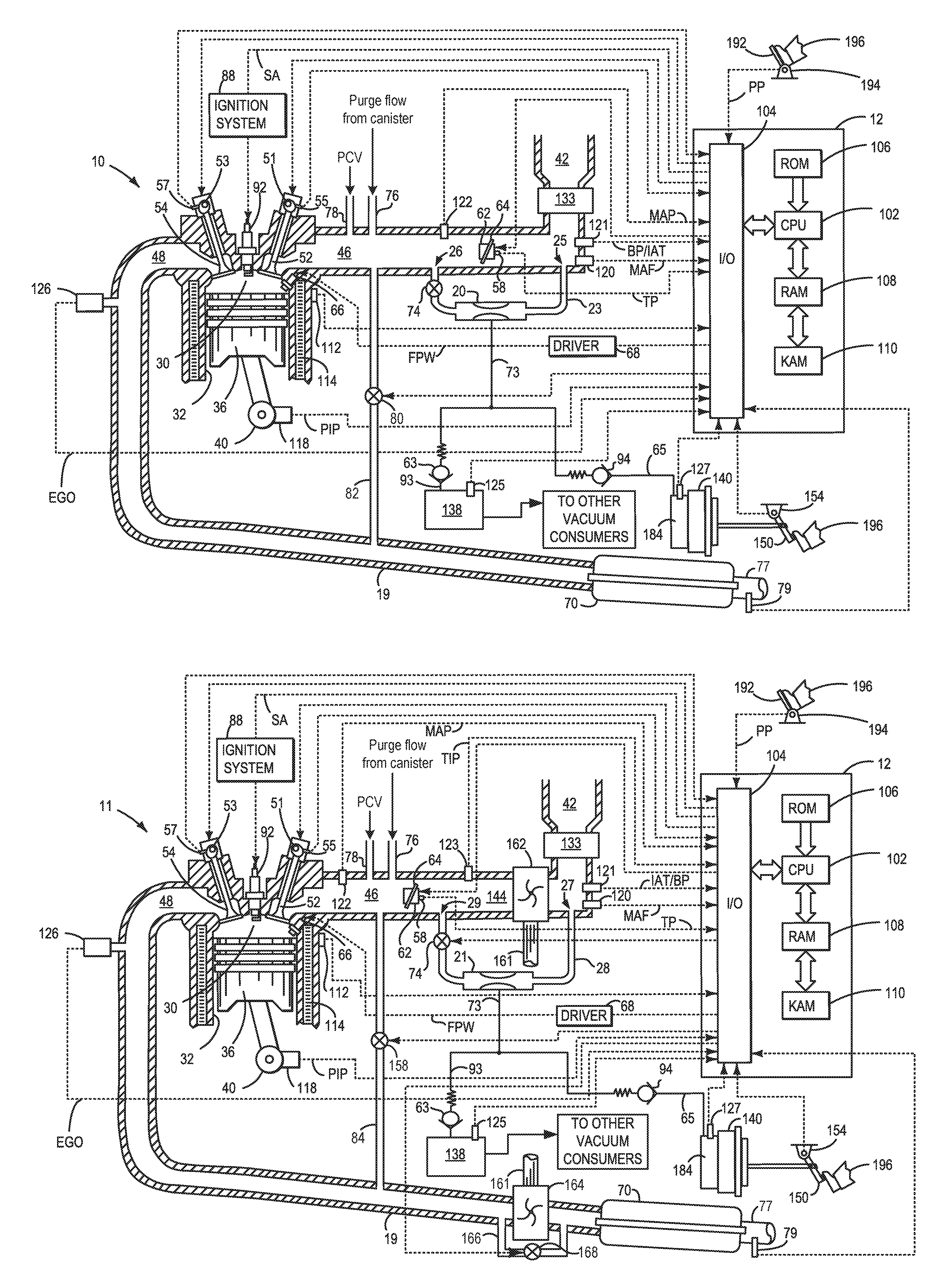
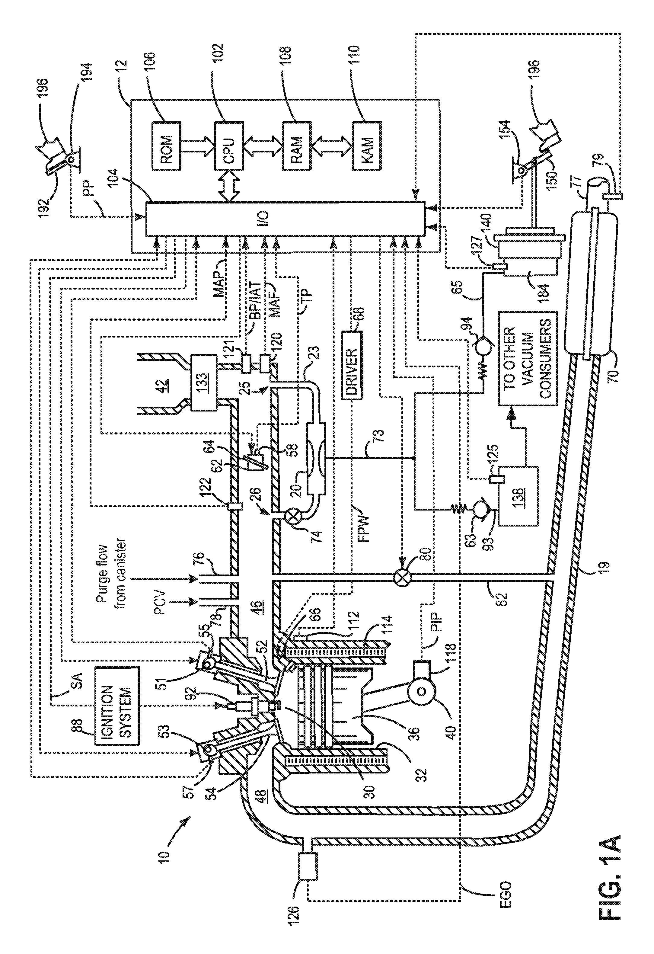
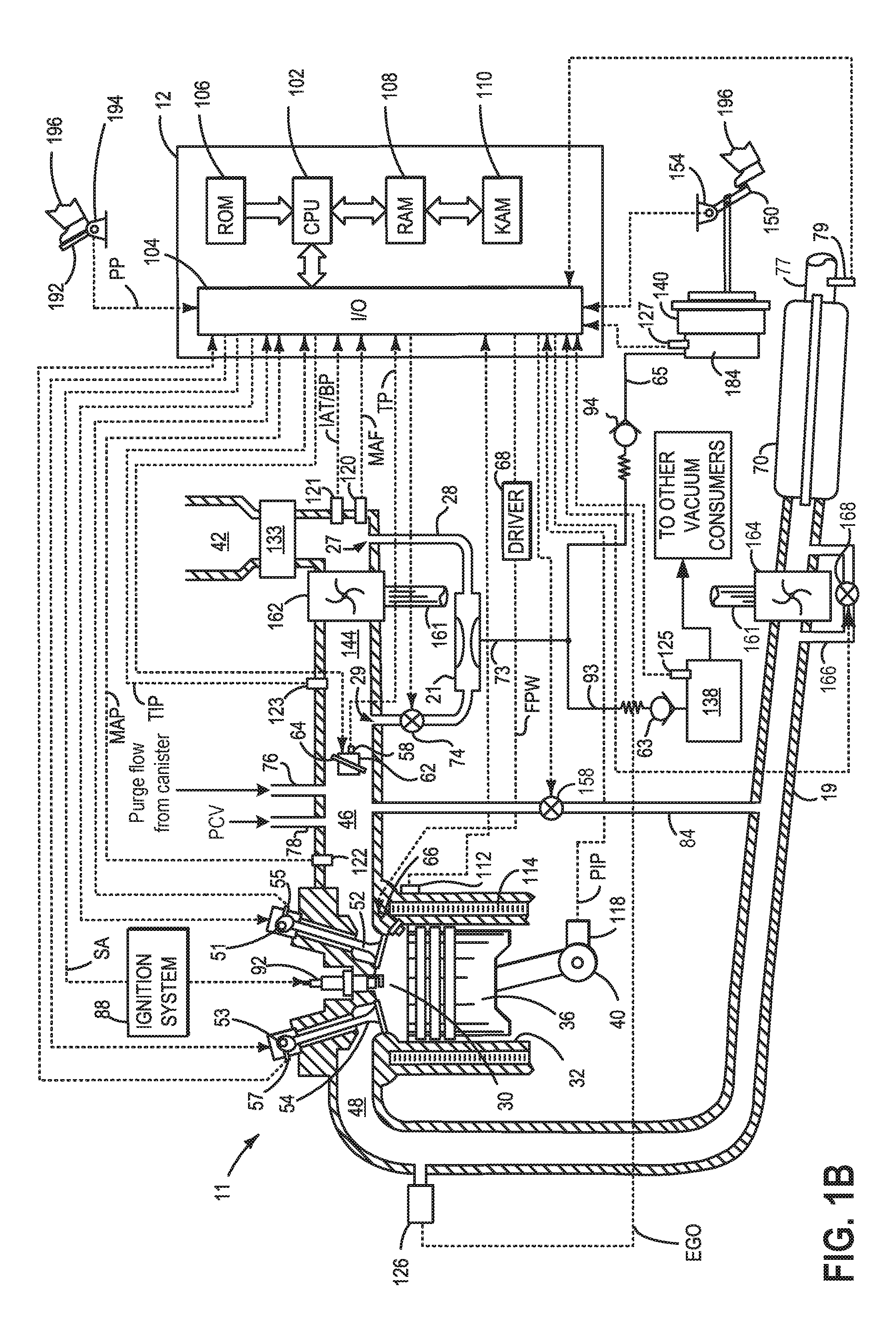
[0027]The following detailed description relates to methods and systems for generating vacuum at an aspirator coupled to an engine system, such as the naturally aspirated engine system of FIG. 1A and the forced induction engine system of FIG. 1B. The engine system may be included in a hybrid electric vehicle (HEV), such as the hybrid vehicle system shown in FIG. 2. Vacuum generation at the aspirator may be regulated by an aspirator shut-off valve (ASOV) coupled either upstream or downstream of the aspirator. As such, an opening of the ASOV may be adjusted to control motive flow through the aspirator, thus, controlling an amount of vacuum generated at the aspirator. A controller may be configured to perform one or more control routines, such as the example routines of FIGS. 3-10, to open or close the ASOV based on engine conditions (FIGS. 3 and 4) such as engine speed (FIG. 6), a temperature of the ASOV (FIG. 8) which may depend on a current and voltage provided to the ASOV (FIG. 9),...


PUM


Abstract

Methods and systems are provided for controlling an aspirator shut-off valve in an engine of a hybrid vehicle. One example method includes opening the aspirator shut-off valve following a shut-down command to the engine when engine speed is between a first engine speed and a second engine speed, the first engine speed being lower than an idle speed and the second engine speed occurring before an imminent engine stop. The example method further includes not opening the aspirator shut-off valve between the first engine speed and the second engine speed if an oxygen content of an emission control device is at or near a threshold.

Description

FIELD[0001]The present invention relates to controlling motive flow through an ejector coupled to an engine in a hybrid vehicle system.BACKGROUND AND SUMMARY[0002]Hybrid electric vehicles (HEV's) utilize a combination of an internal combustion engine with an electric motor to provide the power needed to propel a vehicle. This arrangement provides improved fuel economy over a vehicle that has only an internal combustion engine in part due to the engine being shut down during times when the engine operates inefficiently, or is not otherwise needed to propel the vehicle. During these conditions, the vehicle is transitioned from an engine mode to an electric mode where the electric motor is used to provide all of the power needed to propel the vehicle. When the driver power demand increases such that the electric motor can no longer provide enough power to meet the demand, or if the battery state of charge (SOC) drops below a certain level, the engine is restarted. Vehicle propulsion is...

Claims


Application Information

Patent Timeline
Patent Type & Authority Applications(United States)
IPC IPC(8): B60W20/00F02M35/16F02M35/10
CPCB60W20/00B60W2510/0614F02M35/16F02M35/10229F02D41/042F02D2250/41B60K6/48B60T13/52B60T17/02B60W10/30B60T13/72F02D41/1454F02D2200/101F02D2250/28B60W2510/06B60W2510/0638B60W2510/0657B60W2510/0671B60W2510/244B60W2710/0644Y10S903/902Y02T10/62B60W50/02B60W2710/0677
Inventor LUEHRSEN, ERICPURSIFULL, ROSS DYKSTRA
Owner FORD GLOBAL TECH LLC
Why Eureka
Try Eureka