Aspirator motive flow control for vacuum generation and compressor bypass

a technology of vacuum generation and compressor bypass, applied in the field of engine systems, can solve problems such as compressor degradation, performance problems, and incorporation of such valves, and achieve the effect of expanding the operating region of the engin

Active Publication Date: 2016-07-05
FORD GLOBAL TECH LLC
View PDF5 Cites 8 Cited by
  • Summary
  • Abstract
  • Description
  • Claims
  • Application Information

AI Technical Summary

Benefits of technology

[0002]Turbocharging an engine allows the engine to provide power similar to that of a larger displacement engine. Thus, turbocharging can extend the operating region of an engine.
[0003]Turbochargers function by compressing intake air in a compressor via a turbine operated by exhaust gas flow. Under certain conditions, the flow rate and pressure ratio across the compressor can fluctuate to levels that may result in noise disturbances, and in more severe cases, performance issues and compressor degradation. Such compressor surge may be mitigated by one or more compressor bypass valves (CBVs). The CBVs may recirculate compressed air from the compressor outlet to the compressor inlet, and thus may be arranged in a passage which is coupled to the intake upstream of the compressor and downstream of the compressor in some examples. In some examples, continuous CBVs (CCBVs) may be used, which provide a continuous and continually variable circulation flow from downstream of the compressor to upstream of the compressor. CCBVs may provide boost control and compressor surge avoidance, and may further prevent objectionable audible noise. However, incorporation of such valves can add significant component and operating costs to engine systems.
[0004]Engines may also include one or more aspirators may be coupled in an engine system to harness engine airflow for generation of vacuum, for use by various vacuum consumption devices that are actuated using vacuum (e.g., a brake booster). Aspirators (which may alternatively be referred to as ejectors, venturi pumps, jet pumps, and eductors) are passive devices which provide low-cost vacuum generation when utilized in engine systems. An amount of vacuum generated at an aspirator can be controlled by controlling the motive air flow rate through the aspirator. For example, when incorporated in an engine intake system, aspirators may generate vacuum using energy that would otherwise be lost to throttling, and the generated vacuum may be used in vacuum-powered devices such as brake boosters. While aspirators may generate vacuum at a lower cost and with improved efficiency as compared to electrically-driven or engine-driven vacuum pumps, their use in engine intake systems has traditionally been constrained by both available intake manifold vacuum and maximum throttle bypass flow. Some approaches for addressing this issue involve arranging a valve in series with an aspirator, or incorporating a valve into the structure of an aspirator. Such valves may be referred to as aspirator shut-off valves (ASOVs). An opening amount of the valve is then controlled to control the motive air flow rate through the aspirator, and thereby control an amount of vacuum generated at the aspirator. By controlling the opening amount of the valve, the amount of air flowing through the aspirator and the suction air flow rate can be varied, thereby adjusting vacuum generation as engine operating conditions such as intake manifold pressure change. However, again, adding valves to engine systems which already include various valves serving other purposes (such as CBVs) can add significant component and operating costs.
[0006]While aspirators each having a single tap or suction port may be used, the inventors herein have recognized that a multiple tap aspirator which includes suction taps in the throat, diverging cone, and straight exit tube of the aspirator may advantageously maximize vacuum generation while enabling a high suction flow rate, in that this placement combines the advantages of throat tap aspirators (e.g., high vacuum generation) with the advantages of aspirators with taps arranged downstream of the throat (e.g., high suction flow). Inclusion of a tap in the exit tube (e.g., a straight, unconstricted tube downstream of the aspirator's diverging cone) advantageously enables fast pull-down of a vacuum source, such as a brake booster. Further, the inventors have recognized that such an aspirator may be powered by vacuum rather than compressed air, and that flow losses which often occur in staged aspirators featuring multiple check valves in the suction flow path may be reduced via a configuration wherein only a single check valve in the path between the source of suction flow and each suction tap of the aspirator.

Problems solved by technology

Under certain conditions, the flow rate and pressure ratio across the compressor can fluctuate to levels that may result in noise disturbances, and in more severe cases, performance issues and compressor degradation.
However, incorporation of such valves can add significant component and operating costs to engine systems.
However, again, adding valves to engine systems which already include various valves serving other purposes (such as CBVs) can add significant component and operating costs.

Method used


Image

  • Aspirator motive flow control for vacuum generation and compressor bypass
  • Aspirator motive flow control for vacuum generation and compressor bypass
  • Aspirator motive flow control for vacuum generation and compressor bypass

Examples


Embodiment Construction

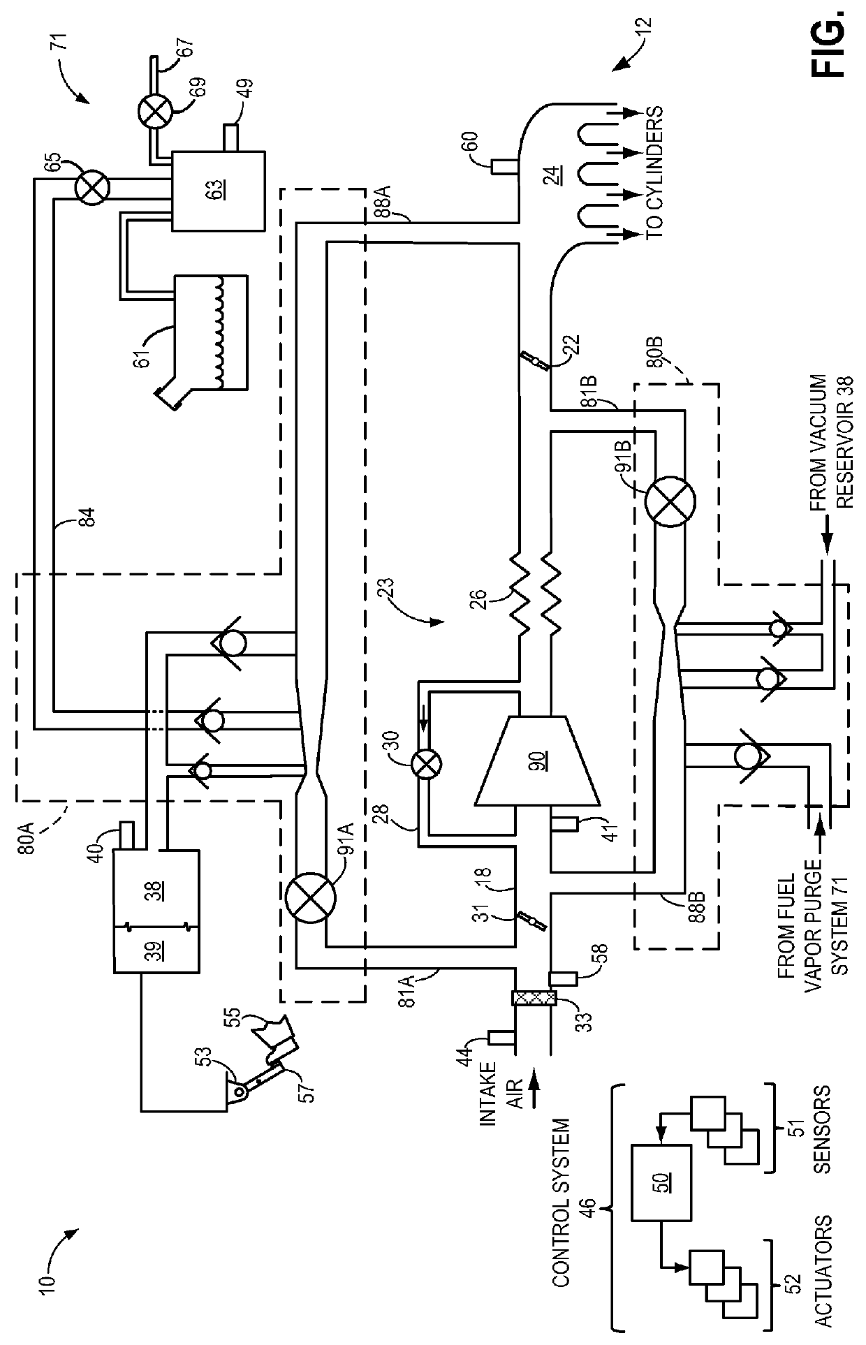
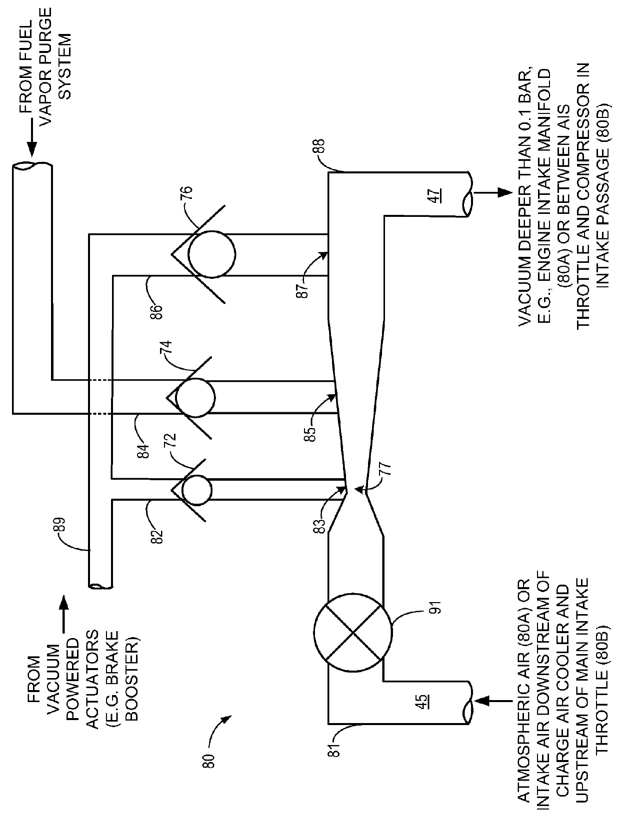
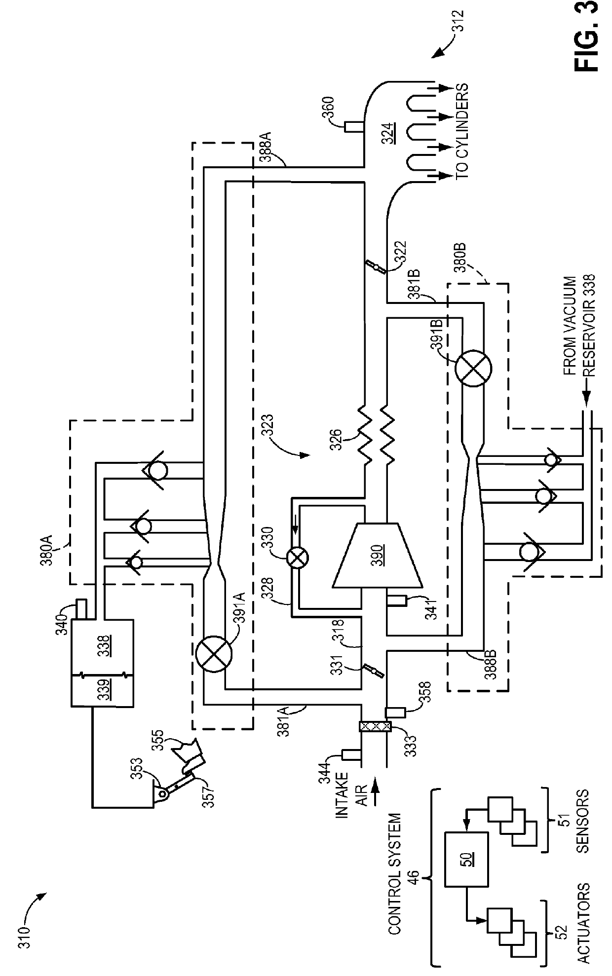
[0019]A first multiple tap aspirator with a motive inlet coupled upstream of a compressor and a mixed flow outlet coupled downstream of a throttle may generate vacuum during non-boost conditions, and may provide compressor bypass flow during compressor bypass flow while continuing to generate some vacuum. Similarly, a second multiple tap aspirator with a motive inlet coupled downstream of a compressor and a mixed flow outlet coupled upstream of a compressor may generate vacuum during boost conditions while also providing a path for compressor bypass flow. One or more suction taps of each of the aspirators may be coupled with a fuel vapor purge system, while the remaining suction taps may be coupled with a vacuum reservoir, as in the engine system of FIG. 1. Alternatively, all suction taps of the aspirators may be coupled with a vacuum reservoir, as in the engine system of FIG. 3. Detail views of example multiple tap aspirators are provided in FIGS. 2 and 4. As shown, check valves ma...


PUM


Abstract

Systems and methods are provided for engine systems including a first multiple tap aspirator with a motive inlet coupled to an intake upstream of an air induction system throttle and a mixed flow outlet coupled to an intake manifold, and a second multiple tap aspirator with a motive inlet coupled to the intake upstream of a main throttle and a mixed flow outlet coupled to the intake downstream of the air induction system throttle. During non-boost conditions, intake air may be selectably diverted around a compressor and through the first and / or second aspirator based on desired vacuum generation. During boost conditions, the first and second aspirators may function as compressor bypass valves, and intake air may be selectably directed from downstream of the compressor to upstream of the compressor via the first and / or second aspirator based on a desired compressor bypass flow.

Description

FIELD[0001]The present invention relates to an engine system including aspirators providing both vacuum generation and boost / surge control.BACKGROUND AND SUMMARY[0002]Turbocharging an engine allows the engine to provide power similar to that of a larger displacement engine. Thus, turbocharging can extend the operating region of an engine.[0003]Turbochargers function by compressing intake air in a compressor via a turbine operated by exhaust gas flow. Under certain conditions, the flow rate and pressure ratio across the compressor can fluctuate to levels that may result in noise disturbances, and in more severe cases, performance issues and compressor degradation. Such compressor surge may be mitigated by one or more compressor bypass valves (CBVs). The CBVs may recirculate compressed air from the compressor outlet to the compressor inlet, and thus may be arranged in a passage which is coupled to the intake upstream of the compressor and downstream of the compressor in some examples....

Claims


Application Information

Patent Timeline
Patent Type & Authority Patents(United States)
IPC IPC(8): F02M35/10F02M25/08F02B33/44
CPCF02M35/10157F02M35/10163F02M35/10222F02M35/10255F02M35/10229F02M25/089F02M35/10019F02M35/10118F02B33/44Y02T10/144Y02T10/12
Inventor PURSIFULL, ROSS DYKSTRA
Owner FORD GLOBAL TECH LLC
Why Eureka
Try Eureka