Multiple tap aspirator with leak passage

a technology of leakage passage and aspirator, which is applied in the direction of combustion engine, combustion air/fuel air treatment, charge feed system, etc., can solve the problems of vacuum reservoir vacuum loss, inability to use, and various disadvantages of aspirators, and achieve the effect of low-cost vacuum generation

Active Publication Date: 2016-03-29
FORD GLOBAL TECH LLC
View PDF9 Cites 4 Cited by
  • Summary
  • Abstract
  • Description
  • Claims
  • Application Information

AI Technical Summary

Benefits of technology

[0002]Vehicle engine systems may include various vacuum consumption devices that are actuated using vacuum. These may include, for example, a brake booster. Vacuum used by these devices may be provided by a dedicated vacuum pump, such as an electrically-driven or engine-driven vacuum pump. As an alternative to such resource-consuming vacuum pumps, one or more aspirators may be coupled in an engine system to harness engine airflow for generation of vacuum. Aspirators (which may alternatively be referred to as ejectors, venturi pumps, jet pumps, and eductors) are passive devices which provide low-cost vacuum generation when utilized in engine systems. An amount of vacuum generated at an aspirator can be controlled by controlling the motive air flow rate through the aspirator. For example, when incorporated in an engine intake system, aspirators may generate vacuum using energy that would otherwise be lost to throttling, and the generated vacuum may be used in vacuum-powered devices such as brake boosters.
[0005]To address at least some of these issues, the inventors herein have identified a multiple tap aspirator with a design which reduces flow disruption caused by the suction tap in the diffuser and also maximizes forward flow of the diffuser suction tap. In one example, an engine system includes an aspirator, bypassing a compressor, a vacuum source coupled with throat and diffuser taps of the aspirator via respective first and second passages merging into a common passage downstream of the vacuum source, the first and second passages coupled by a leak passage with a flow restriction, a first check valve arranged in the common passage, and a second check valve arranged in the second passage upstream of the leak passage. An exit of the diffuser tap narrows as it approaches the diffuser, and the throat tap and a nozzle of the aspirator together form a converging annular suction flow path into the throat of the aspirator. During conditions when the pressure at the vacuum source is higher than the pressures at the diffuser tap and throat tap, there is forward flow from the vacuum source into both taps (assuming motive flow through the aspirator is present). While the pressure tends to be lower at the throat tap, the flow is restricted there due to the converging annular suction flow path into the throat formed by the throat tap and the nozzle, and thus the majority of the suction flow may advantageously enter the diffuser tap to provide extra suction flow as compared to a single-tap aspirator. Further, in some examples, the exit of the diffuser tap may be substantially parallel to the axis of the diffuser, such that the suction flow entering the diffuser tap is already traveling in the same direction as the motive flow through the diffuser, thereby reducing flow disruption at the diffuser tap.
[0006]In contrast, when the pressure at the vacuum source is lower than the pressure at the diffuser tap in the above example, a check valve closes and reverse flow into the diffuser tap (“backflow”) may occur. A special technical effect achieved is that this backflow travels from the diffuser tap into the throat tap, which may advantageously produce an effect similar to bleed-gap or hybrid diffusers where the low-velocity boundary layer is sucked out of the diffuser tap, pulling the high-velocity flow near the wall and decreasing the likelihood of flow separation.

Problems solved by technology

Staged aspirators including multiple suction ports or taps may be used, but such aspirators tend to suffer from various disadvantages.
For example, staged aspirators may rely on a motive flow of compressed air, and may not be usable in configurations where motive flow is intermittent (e.g., intermittent motive flow may result in vacuum reservoir vacuum loss in some examples).
A suction tap arranged in the diffuser of an aspirator may act as an initiation site for flow separation, which may render the rest of the diffuser ineffective.
Because obtaining a deep vacuum at the throat suction tap of an aspirator is highly dependent on the effectiveness of the diffuser, flow separation caused by any additional suction taps in the diffuser of an aspirator may significantly degrade the aspirator's ability to generate vacuum.
These features may be difficult to incorporate for suction taps arranged in the diffuser of an aspirator, and thus may often disadvantageously be neglected in staged aspirators.

Method used


Image

  • Multiple tap aspirator with leak passage
  • Multiple tap aspirator with leak passage
  • Multiple tap aspirator with leak passage

Examples


first embodiment

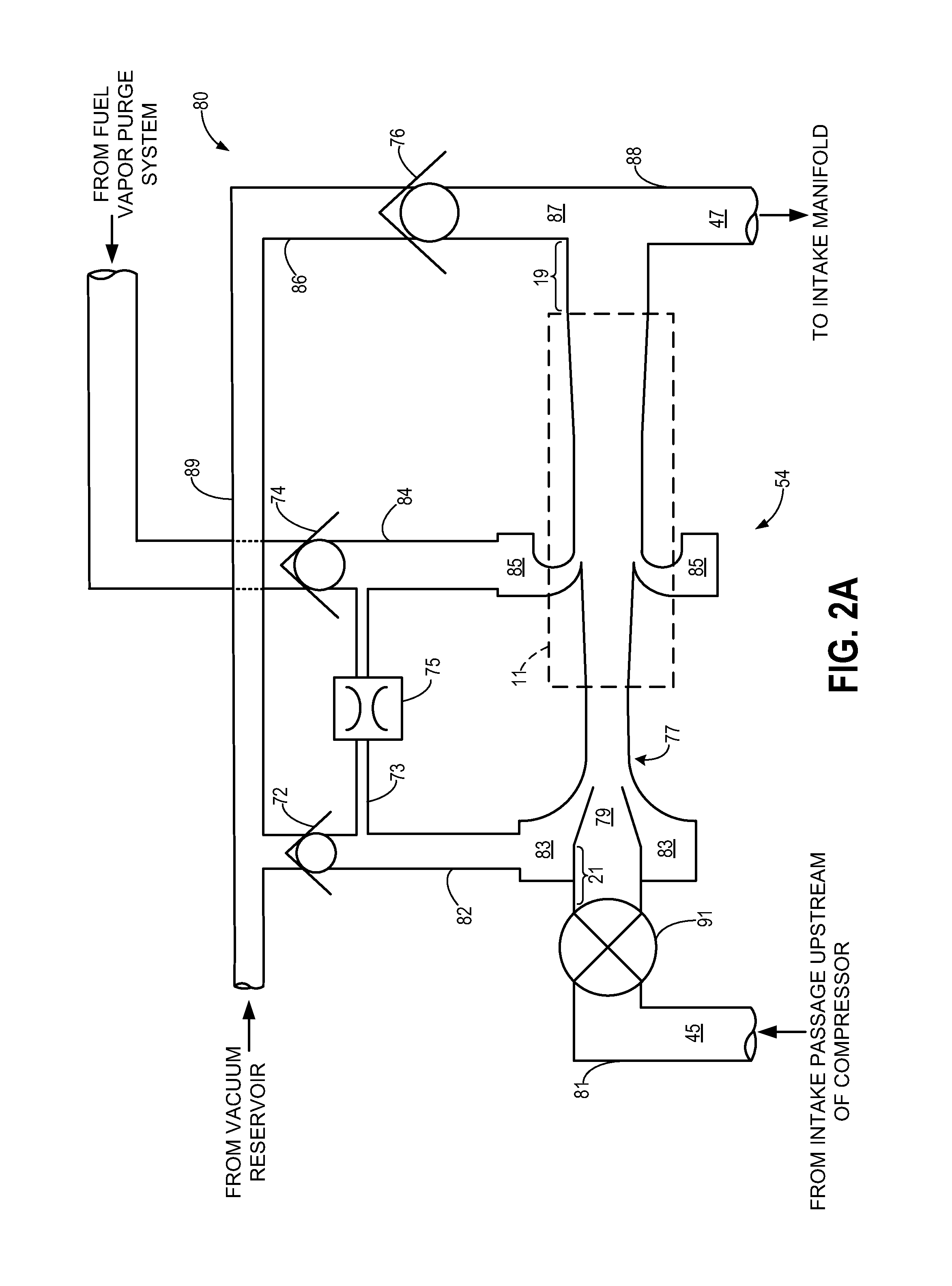
[0056]In contrast to diffuser 11 of the aspirator shown in FIGS. 2A-B, diffuser 11 of FIGS. 2C-D may have a diverging flow geometry along its entire length, such that it lacks a constant-diameter portion such as first constant-diameter portion 15 of FIG. 2B. As shown, the sides of the diffuser diverge at a constant angle of divergence (the angle between dashed line 25 and each of dashed lines 27). Accordingly, whereas the diffuser shown in FIG. 2B is designed such that the effectiveness of the diffuser tap is prioritized over the effectiveness of the throat tap, the diffuser shown in FIG. 2D is designed such that the effectiveness of the throat tap is prioritized over the effectiveness of the diffuser tap. Turning to FIGS. 9A-B, they depict an aspirator arrangement 900 which may correspond to aspirator arrangement 80 of the These figures depict suction and motive flow through aspirator arrangement 900 for different system pressure levels when the ASOV is open, when the CPV of the f...

second embodiment

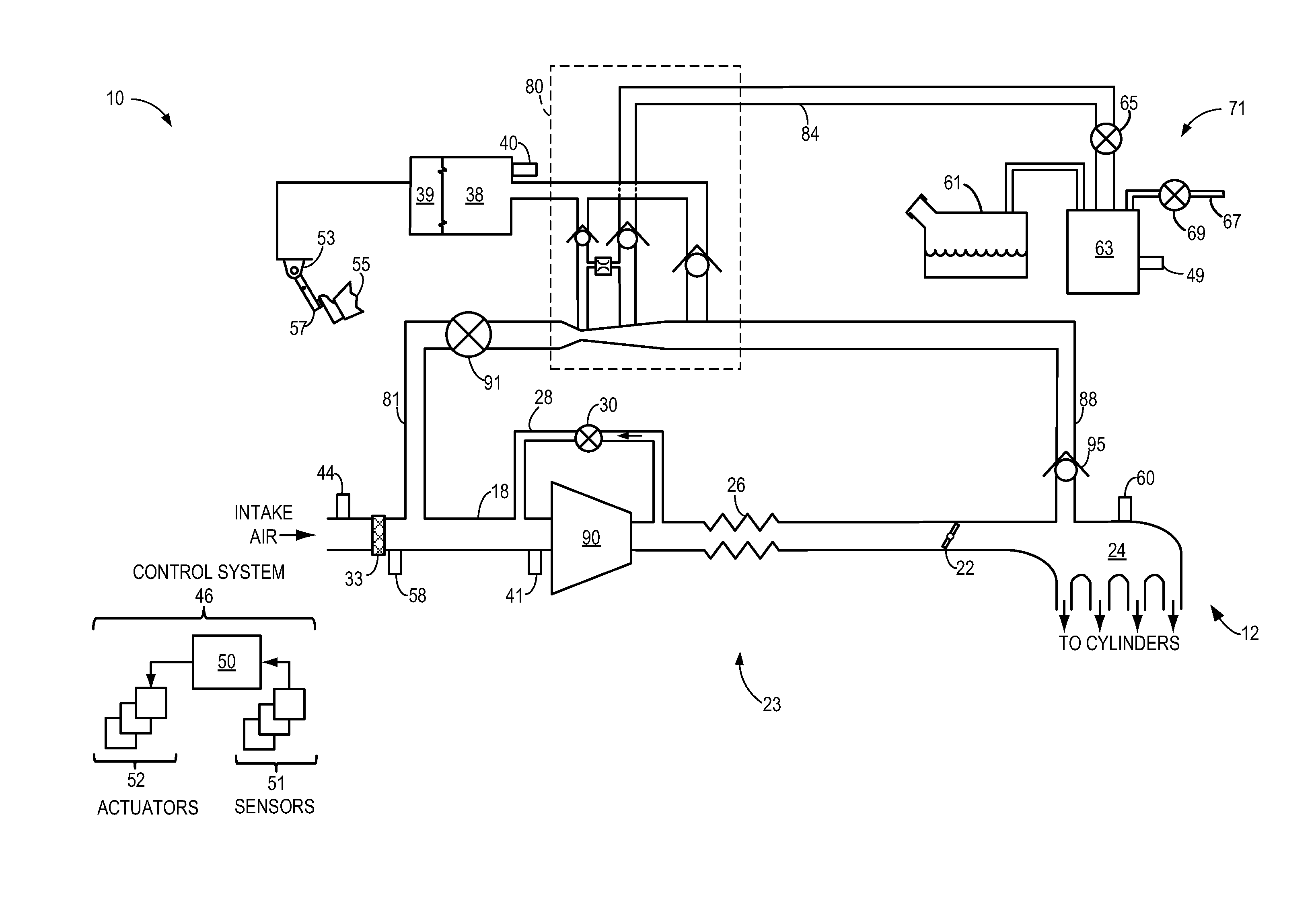
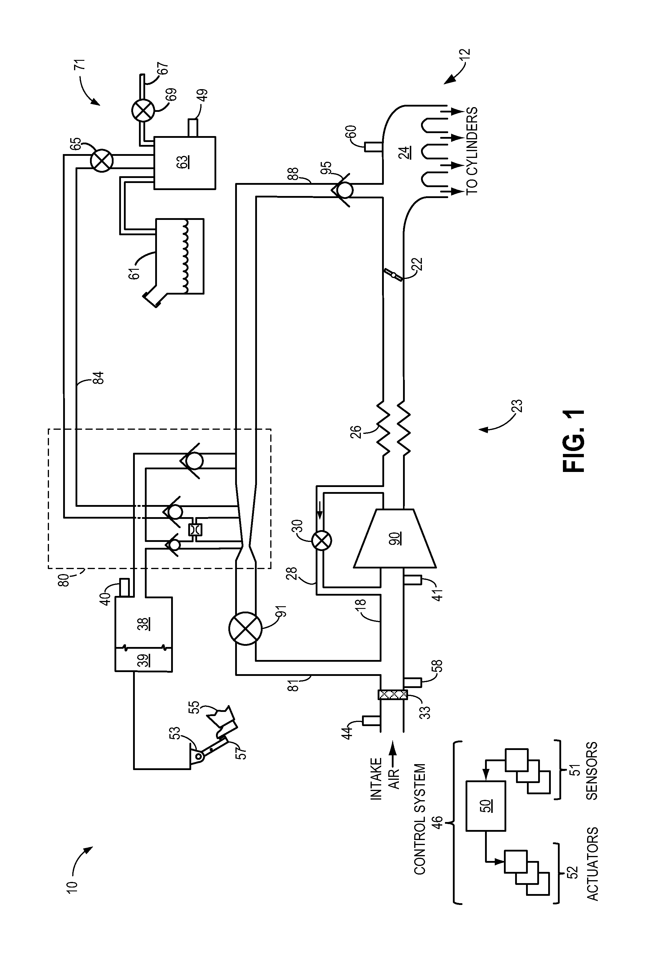
[0060]an engine system including a multiple tap aspirator is depicted in FIGS. 3-4. The second embodiment includes many of the same features described above for the first embodiment; similar features are numbered similarly and will not be described again for the sake of brevity. Further, it will be appreciated that various features among the two embodiments are usable together. For example, the aspirator arrangement of FIG. 3 may be configured in accordance with FIG. 2A or FIG. 2C rather than FIG. 4, or the aspirator arrangement of FIG. 1 may be configured in accordance with FIG. 4 rather than FIG. 2A or FIG. 2C, without departing from the scope of this disclosure. Furthermore, in the depicted second embodiment, diffuser 11 shown in FIG. 4 may correspond to diffuser 11 depicted in FIG. 2B or alternatively diffuser 11 depicted in FIG. 2D.

[0061]In contrast to the first embodiment, wherein the motive inlet of the aspirator arrangement fluidly communicates with the intake passage upstre...


PUM


Abstract

Systems and methods are provided for engine systems including a multiple tap aspirator with a throat tap and a diffuser tap. Suction passages coupled to the throat and diffuser taps, respectively, may fluidly communicate via a leak passage with a flow restriction. During conditions where the pressure at a suction flow source of the diffuser tap is less than the pressure at the diffuser tap, backflow from the diffuser tap may travel through the leak passage into the throat tap.

Description

FIELD[0001]The present application relates to an engine system incorporating a multiple tap aspirator which may generate vacuum and / or provide compressor recirculation flow, where flow separation at a diffuser tap of the aspirator is minimized via backflow into a leak passage coupling the diffuser tap with a throat tap of the aspirator.BACKGROUND AND SUMMARY[0002]Vehicle engine systems may include various vacuum consumption devices that are actuated using vacuum. These may include, for example, a brake booster. Vacuum used by these devices may be provided by a dedicated vacuum pump, such as an electrically-driven or engine-driven vacuum pump. As an alternative to such resource-consuming vacuum pumps, one or more aspirators may be coupled in an engine system to harness engine airflow for generation of vacuum. Aspirators (which may alternatively be referred to as ejectors, venturi pumps, jet pumps, and eductors) are passive devices which provide low-cost vacuum generation when utilize...

Claims


Application Information

Patent Timeline
Patent Type & Authority Patents(United States)
IPC IPC(8): F02M35/10
CPCF02M35/10157F02M35/10222F02M35/10229F02M35/10144Y02T10/12F02M35/10118F02M35/10209F02M35/10236
Inventor VANDERWEGE, BRAD, ALAN
Owner FORD GLOBAL TECH LLC
Why Eureka
Try Eureka