Microphone

a microphone and microphone technology, applied in the field of microphones, can solve the problems of reducing the degree of freedom of layout, unable to provide the microphone terminal on the rigid substrate, and imposing restrictions on the layout of the mems capacitor inside the housing, so as to reduce the noise resistance, increase the degree of freedom, and the effect of reducing the noise resistan

Inactive Publication Date: 2013-12-10
HOSIDEN CORP
View PDF8 Cites 14 Cited by
  • Summary
  • Abstract
  • Description
  • Claims
  • Application Information

AI Technical Summary

Benefits of technology

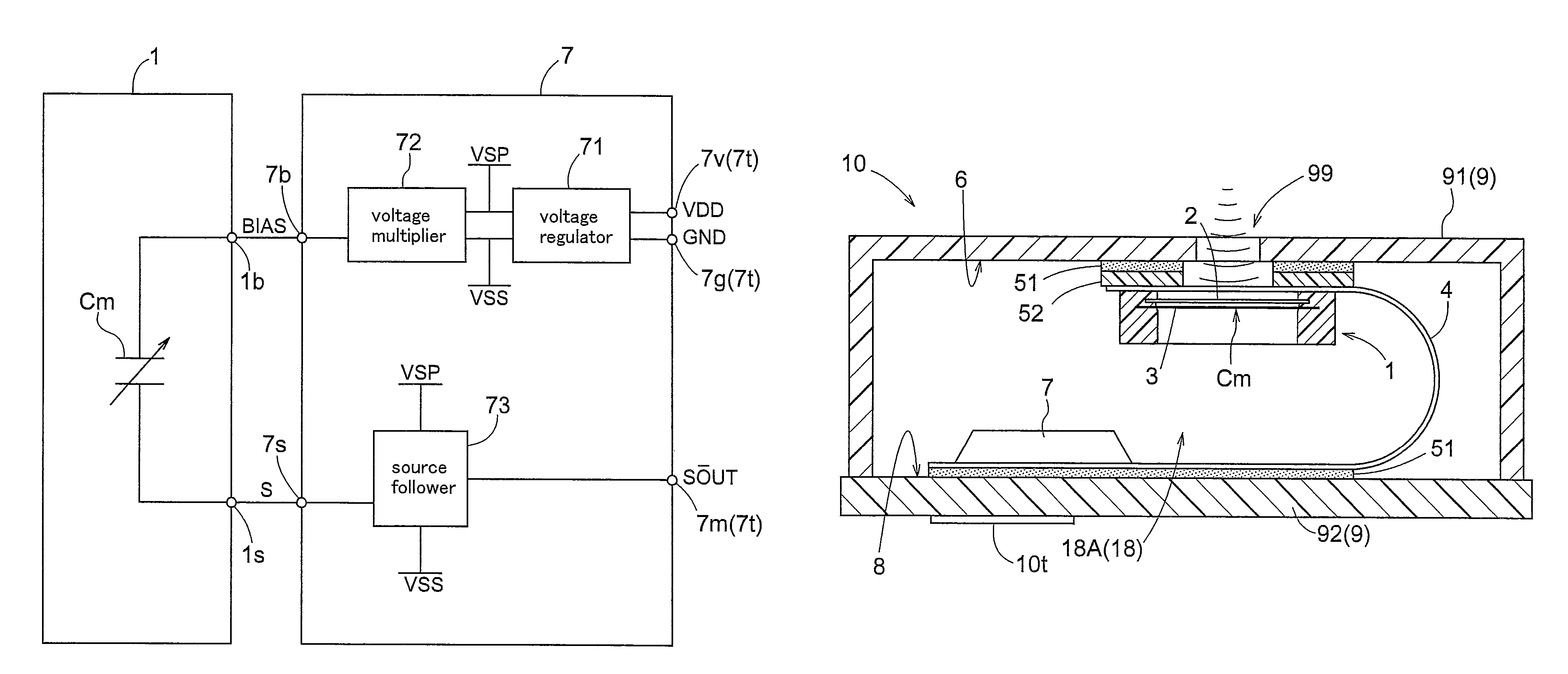
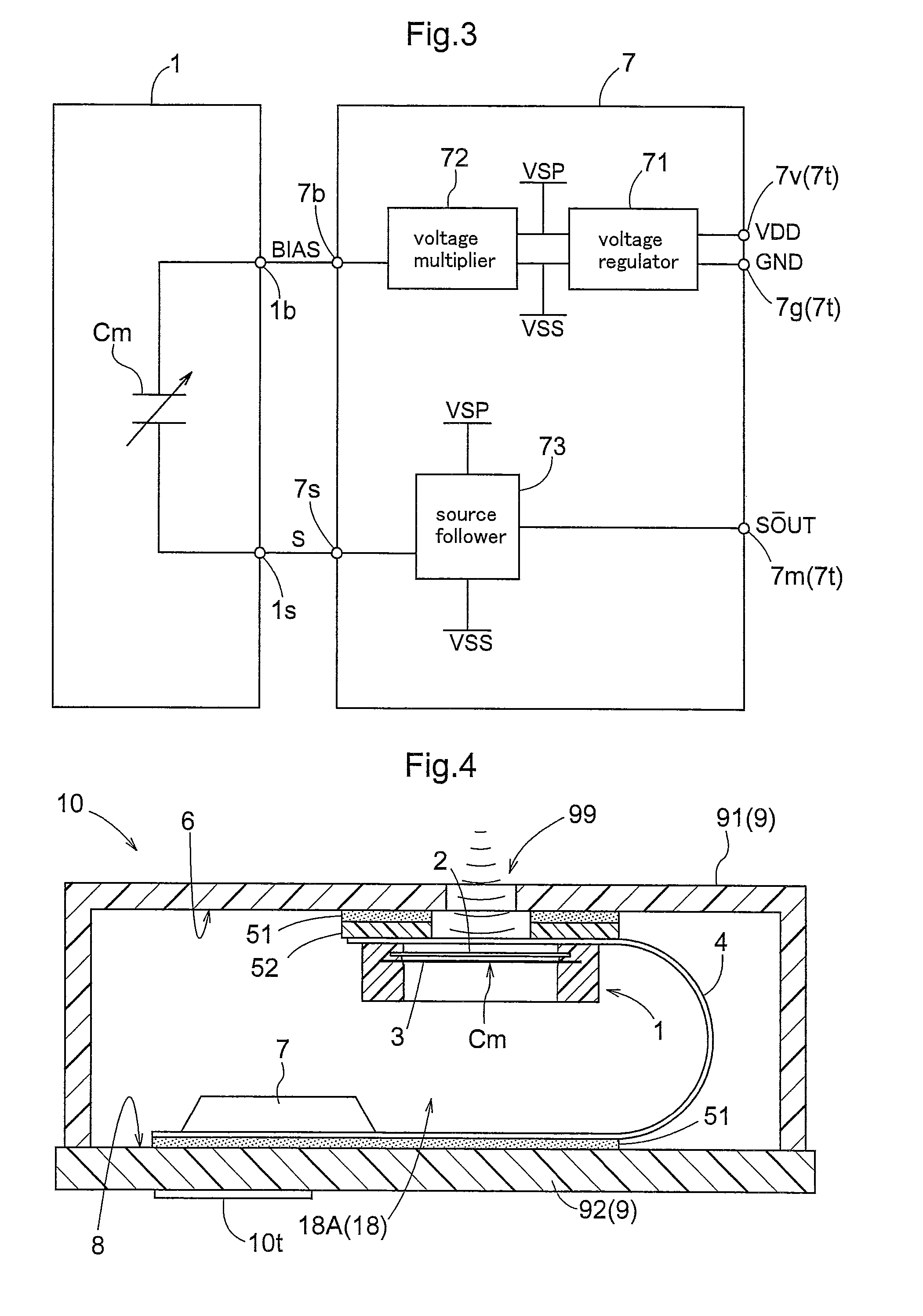
[0015]With this characterizing feature, as there is provided a flexible substrate having a wire for electrical connection between the MEMS capacitor and the detecting circuit that are secured to the first face and the second face not adjacent each other inside the housing, the MEMS capacitor and the detecting circuit can be mounted separately on two different faces. Therefore, as the MEMS capacitor and the detecting circuit are connected via the flexible substrate, there is no mechanical connection involved, so it is possible to restrict signal decay in the detection signal of the MEMS capacitor and the reduction in the noise resistance. Further, with the separate mounting of the MEMS capacitor and the detecting circuit on the two different faces, the restriction imposed on the layout of the MEMS capacitor inside the housing is relaxed and there is provided greater degree of freedom in the layout. The size of the back chamber of the MEMS capacitor affects the acoustic characteristics, as described above. In this regard, with the increased degree of freedom in the layout of the MEMS capacitor inside the housing, it becomes easier to obtain desired advantageous acoustic characteristics. Further, as described also above, the size of the back chamber in the MEMS capacitor per se depends upon the size of the trench formed in the MEMS capacitor. In this respect, with the above-described characterizing feature of the invention, the size of the back chamber as a microphone can be determined with taking into consideration not only the size of the trench of the MEMS capacitor per se, but also the space available inside the housing. Therefore, it becomes possible to apply the same MEMS capacitor in various microphones having various housings, so that the cost reduction advantage due to mass production can be obtained more easily.
[0016]Preferably, the flexible substrate of the inventive microphone is configured such that the MEMS capacitor is mounted in the area of the flexible substrate secured to said first face. Also, preferably, the flexible substrate of the inventive microphone is configured such that the detecting circuit is mounted in the area of the flexible substrate secured to said second face. The flexible substrate that can be bent inside the housing can mount and secure such components as the MEMS capacitor or the detecting circuit on either one or both of the faces thereof not adjacent each other. As the flexible substrate is secured to both the first face and the second face of the housing, the component mounted and secured to this flexible substrate is secured to the first face and the second face of the housing. For instance, if a component is mounted to either one of them, this mounted component and the wiring electrically connecting the two faces will be constructed as an assembly of one flexible substrate. If the MEMS capacitor and the wire are constructed as a single assembly, application to various microphones having many kinds of detecting circuits and many kinds of housings in combination is made possible. Similarly, if the detecting circuit and the wire are constructed as a single assembly, application to various microphones having many kinds of MEMS capacitors and many kinds of housings in combination is made possible. Accordingly, the cost reduction advantage due to mass production can be obtained more easily.
[0017]Meanwhile, the flexible substrate can alternatively be configured such that such components as the MEMS capacitor and the detecting circuit can be mounted and secured to both of the two non-adjacent faces thereof to which this flexible substrate is secured. Therefore, needless to say, the flexible substrate of the inventive microphone can be configured such that the MEMS capacitor is mounted in the area thereof secured to the first face and the detecting circuit is mounted in the area thereof secured to the second face. Then, if the MEMS capacitor, the detecting circuit and the wire are constructed altogether as a single assembly, application to various kinds of microphones having various kinds of housing becomes easier and the cost reduction advantage due to mass production can be obtained more easily.
[0018]Preferably, said detecting circuit of the inventive microphone is comprised of a single integrated circuit. With this, the components mounted inside the housing become substantially two, i.e. the MEMS capacitor and the integrated circuit. Hence, the productivity will be improved and application to multi-product publication becomes easier.

Problems solved by technology

However, with the top acoustic hole type microphone of this type, it is not possible to provide the microphone terminal on the rigid substrate mounting the MEMS capacitor and the IC chip.
Therefore, there is necessarily imposed restriction on the layout of the MEMS capacitor within the housing member.
And, the disposing position of the substrate imposes restriction on the layout of the MEMS capacitor inside the housing.
However, with this connection arrangement comprising two rigid substrates electrically connected to each other, as the connection method is mechanical, the electric resistance is high, so that decay of signals, reduction in the noise resistance can be invited.
Further, the acoustic chamber of the MEMS capacitor affects the acoustic characteristics.
As a result, it becomes difficult to employ a common MEMS capacitor in various microphones having various housings.
As a result, it will become difficult to achieve mass production cost reduction advantage. FIG. 10 in Japanese Patent Application “Kokai” No. 2007-329560 shows an example wherein the back chamber is enlarged by cutting away the substrate (rigid substrate).
This arrangement, however, has may disadvantages in the respect of production cost.

Method used


Image

  • Microphone
  • Microphone
  • Microphone

Examples


Embodiment Construction

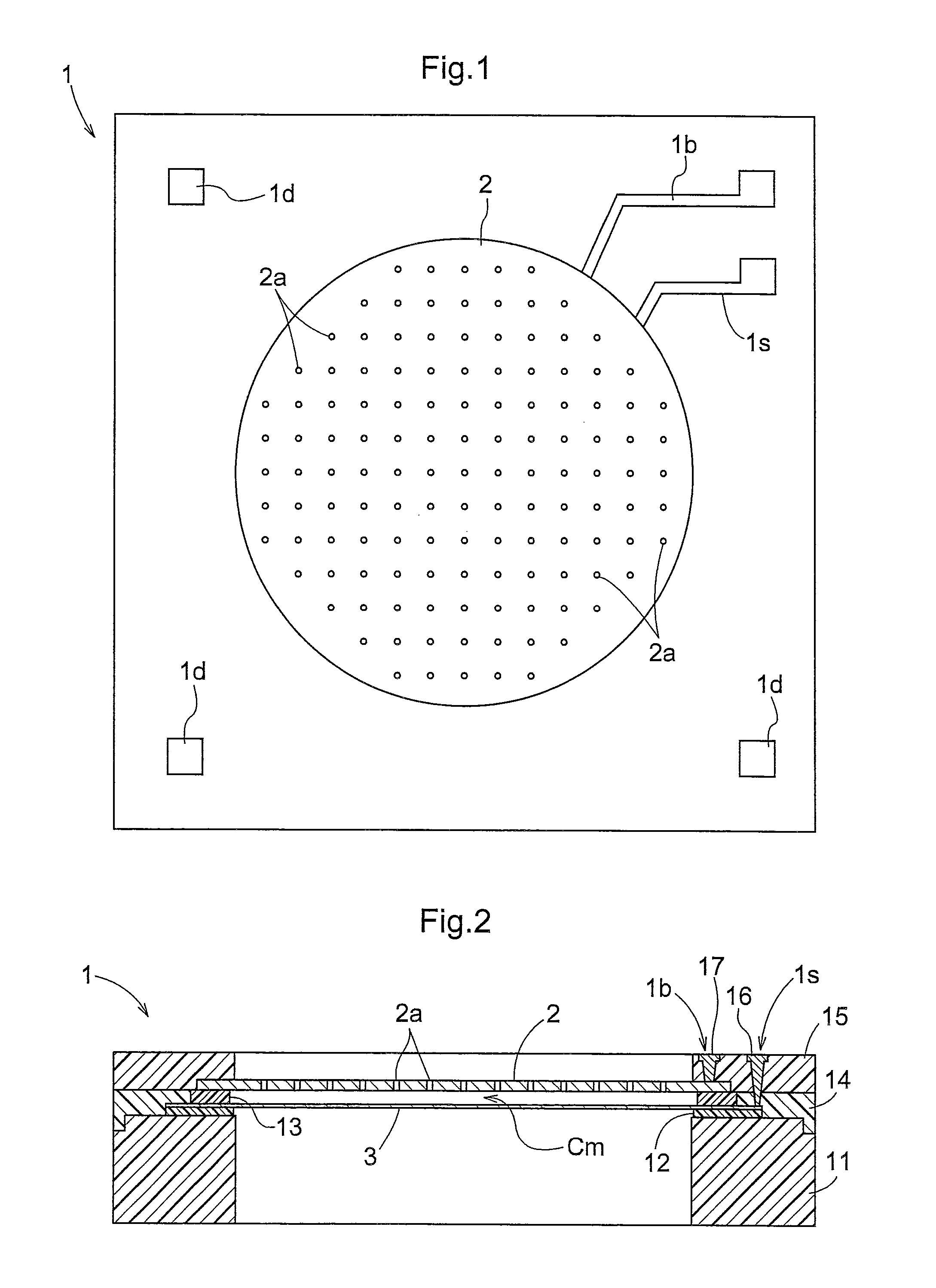
[0029]Next, embodiments of the present invention will be described with reference to the accompanying drawings. An MEMS capacitor 1, as is well-known, is a capacitor manufactured by the MEMS (micro electro mechanical systems) technique, with using a semiconductor processing technique from a monocrystal silicon substrate. As shown in FIG. 1 and FIG. 2, the MEMS capacitor 1 includes a back electrode plate 2 defining many holes 2a, and a diaphragm plate 3 which oscillates in response to a sound. Between the back electrode plate 2 and the diaphragm plate 3, a space is created to form a capacitor Cm. The back electrode plate 2 and the diaphragm plate 3 are formed of electrically conductive material. The back electrode plate 2 is connected to an electrode 17 which forms a terminal 1b on the outer surface of the MEMS capacitor 1. Further, the diaphragm plate 3 is connected to an electrode 16 which forms a terminal is on the outer surface of the MEMS capacitor 1. Between a silicon substrate...


PUM


Abstract

A microphone has a housing (9) defining an acoustic hole (99) and having inner faces. The microphone includes a MEMS capacitor (1) secured to and electrically connected with a first face (6) of the inner faces of the housing (9), the first face defining the acoustic hole (99), a detecting circuit (7) secured to and electrically connected with a second face (8) of the inner faces of the housing (9), the second face (8) being not adjacent the first face (6), the detecting circuit (7) detecting at least a change in the electrostatic capacity of the MEMS capacitor (1). The microphone further includes a flexible substrate (4) secured to the first face (6) and the second face (8) and disposed under a bent state inside the housing (9). The flexible substrate (4) establishes electrical connection between the MEMS capacitor (1) and the detecting circuit (7) via a wire electrically connecting the first face (6) and the second face (8).

Description

BACKGROUND OF THE INVENTION[0001]1. Field of the Invention[0002]The present invention relates to a microphone having a MEMS capacitor.[0003]2. Description of the Related Art[0004]In recent years, there have been manufactured small microphones to be mounted in a small electronic instrument such as a mobile phone, an IC reorder, etc. with using the MEMS (micro electro mechanical systems) technique. Japanese Patent Application “Kokai” No. 2007-329560 discloses such a microphone having a capacitor made with the MEMS technique. In this microphone, the MEMS capacitor and a converter circuit comprised of an IC (integrated circuit) are mounted on a common rigid substrate, and over this board, a case having an acoustic hole is placed to complete the microphone. The rigid substrate is formed of a rigid material whose shape does not deform flexibly. The back chamber of the MEMS capacitor is formed within a space created between the MEMS capacitor and the rigid substrate. Further, on the outer ...

Claims


Application Information

Patent Timeline
Patent Type & Authority Patents(United States)
IPC IPC(8): H04R25/00
CPCH04R1/06H04R31/006H04R19/005H01L2224/48091H01L2924/00014H01L2224/45144H01L2924/00H01L2924/3011H01L2924/1461H01L2924/16151H01L2924/16152H04R3/10
Inventor AWAMURA, RYUJIHANADA, NORIAKINAKANISHI, KENSUKETOYODA, TETSUO
Owner HOSIDEN CORP
Why Eureka
Try Eureka