Exhaust gas recirculation device of internal combustion engine, and control method thereof

a technology of exhaust gas recirculation and internal combustion engine, which is applied in the direction of electric control, machines/engines, mechanical equipment, etc., can solve the problems of insufficient supply of egr gas, excessively large or small amount of egr gas recirculated via the low-pressure egr passage, and the inability to supply sufficient egr gas, etc., to achieve good degree of freedom

Inactive Publication Date: 2009-08-06
TOYOTA JIDOSHA KK
View PDF17 Cites 35 Cited by
  • Summary
  • Abstract
  • Description
  • Claims
  • Application Information

AI Technical Summary

Benefits of technology

[0011]In an exhaust gas recirculation device having a low-pressure EGR passage and a control method thereof, the invention makes it possible to suitably accomplish the control of the degree of opening of the exhaust throttle valve and the control of EGR via the low-pressure EGR passage at the same time while securing good degrees of freedom of the two controls.

Problems solved by technology

Therefore, there is a possibility that the adjusting accuracy of a flow amount regulator valve provided on the low-pressure EGR passage will decline and therefore the amount of EGR gas recirculated via the low-pressure EGR passage will become excessively large or small.
In this case, however, during the regeneration process of the filter, there is a possibility that sufficient amount of EGR gas cannot be supplied to the internal combustion engine and therefore the amount of NOx emission will increase.
Conversely, during a state of engine operation that requires large amount of EGR, there is also a possibility that the execution of the regeneration process of the filter will become impossible and therefore an excessive amount of PM will deposit on the filter and will degrade fuel economy.
This problem can possibly occur not only in the case where the exhaust throttle valve is closed at the time of the regeneration process of the filter, but also in, for example, the case where the exhaust throttle valve is closed at the time of quick warm-up of a catalyst, the case where the exhaust throttle valve is closed in order to operate an exhaust brake, etc.

Method used


Image

  • Exhaust gas recirculation device of internal combustion engine, and control method thereof
  • Exhaust gas recirculation device of internal combustion engine, and control method thereof
  • Exhaust gas recirculation device of internal combustion engine, and control method thereof

Examples


Embodiment Construction

[0044]Embodiments for carrying out the invention will be described in detail in an exemplary fashion with reference to the drawings. The sizes, materials, shapes, relative arrangements, and the like of component parts mentioned in conjunction with the embodiments are not intended to limit the technical scope of the invention only to the scope defined by those features and the like of the component parts unless a particularly specific description is provided.

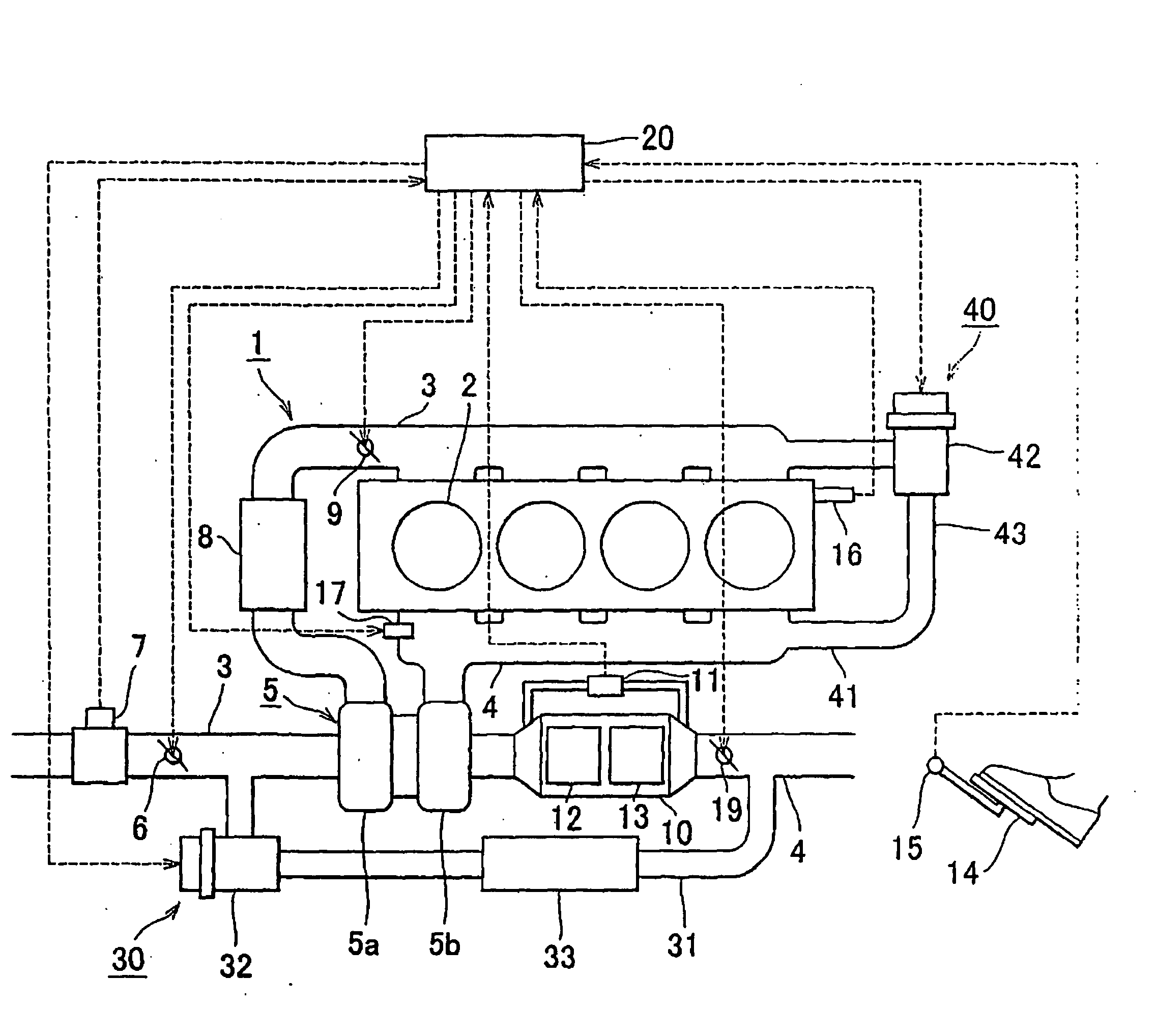
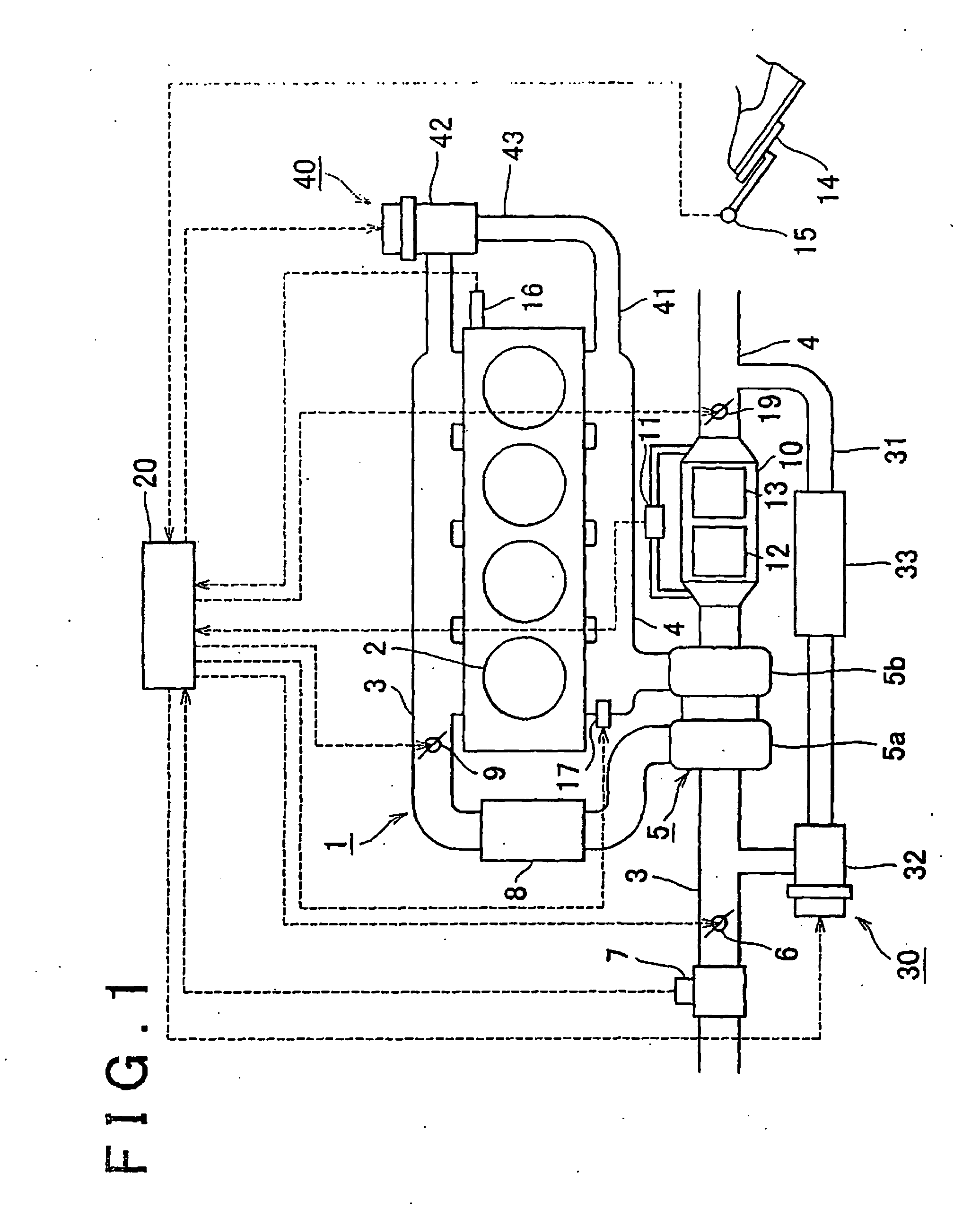
[0045]FIG. 1 is a schematic diagram showing a construction of an internal combustion engine and an intake system and an exhaust system thereof to which an exhaust gas recirculation device in accordance with an embodiment is applied. An internal combustion engine 1 shown in FIG. 1 is a water-cooled four-stroke diesel engine that has four cylinders 2.

[0046]An intake pipe 3 and an exhaust pipe 4 are connected to the internal combustion engine 1. An intermediate portion of the intake pipe 3 is provided with a second intake throttle v...


PUM


Abstract

An exhaust gas recirculation device includes a turbocharger (5) having a turbine (5b) on an exhaust pipe (4) and a compressor (5a) on an intake pipe (3), a low-pressure EGR passage (31) connecting the exhaust pipe (4) downstream of the turbine (5b) and the intake pipe (3) upstream of the compressor (5a), and a filter (13) provided on the exhaust pipe (4) downstream of the turbine (5b). In the device, an exhaust throttle valve (19) is disposed on the exhaust pipe (4) that is downstream of the filter (13) and that is upstream of a site of connection with the low-pressure EGR passage (31).

Description

BACKGROUND OF THE INVENTION[0001]1. Field of the Invention[0002]The invention relates to an exhaust gas recirculation device of an internal combustion engine, and a control method thereof.[0003]2. Description of the Related Art[0004]A known technology of reducing the amount of NOx contained in exhaust gas from an internal combustion engine is an EGR technology that recirculates a portion of exhaust gas to an intake passage. For example, Japanese Patent Application Publication No. JP-A-2004-150319 discloses an exhaust gas recirculation device of an internal combustion engine which includes a low-pressure EGR passage connecting an exhaust passage downstream of a turbine of a turbocharger and an intake passage upstream of a compressor of the turbocharger, and a high-pressure EGR passage connecting the exhaust passage upstream of the turbine and the intake passage downstream of the compressor, and which performs an EGR control by switching between the low-pressure EGR passage and the hi...

Claims


Application Information

Patent Timeline
Patent Type & Authority Applications(United States)
IPC IPC(8): F02M25/07F01N3/00F01N3/02
CPCF01N3/0235F01N13/0097F02B3/06F02B29/0406F02B37/00F02D9/04F02D41/0007F02D41/0055F02D41/024F02D41/029F02D2041/0017F02M25/0707F02M25/0709F02M25/0713F02M25/0718F02M25/0731F02M25/0732F02M25/0744Y02T10/144Y02T10/47F01N3/2006F02M26/05F02M26/06F02M26/10F02M26/15F02M26/28F02M26/24F02M26/38Y02T10/12Y02T10/40
Inventor NAGAE, MASAHIROSHIMIZU, HAJIMEMURATA, HIROKI
Owner TOYOTA JIDOSHA KK
Why Eureka
Try Eureka