Fuel injection valve

a fuel injection valve and valve body technology, applied in the direction of fuel injection apparatus, spraying apparatus, charge feed system, etc., can solve the problems of shortening the side length and degrading the depositing characteristics, and achieve good configuration, suppress the deposition, and improve the degree of freedom of the first injection port

Active Publication Date: 2009-11-05
MITSUBISHI ELECTRIC CORP
View PDF5 Cites 36 Cited by
  • Summary
  • Abstract
  • Description
  • Claims
  • Application Information

AI Technical Summary

Benefits of technology

[0006]The distance between the fuel spray pattern and the inner wall of the second injection port can be increased, so that the depth of the second injection port can be made deeper withou

Problems solved by technology

However, shallow depth of the second injection port makes the degree of freedom of L/D of the first injection port small and, depending upon the inclination angle, necessary length of the inner wall

Method used


Image

  • Fuel injection valve
  • Fuel injection valve
  • Fuel injection valve

Examples


embodiment 1

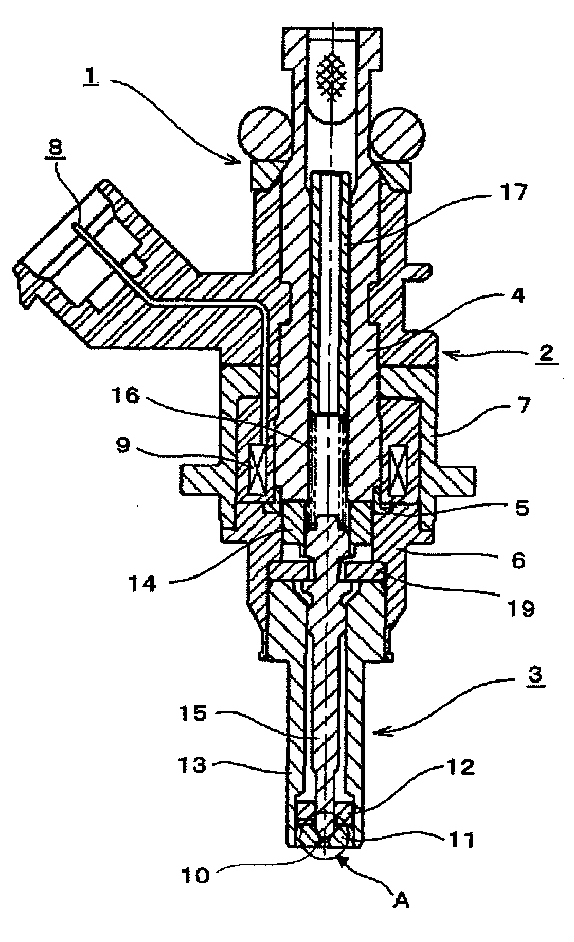
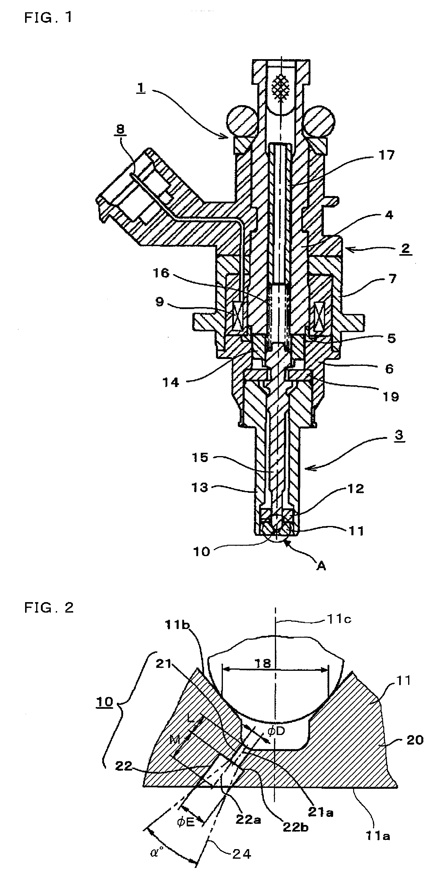
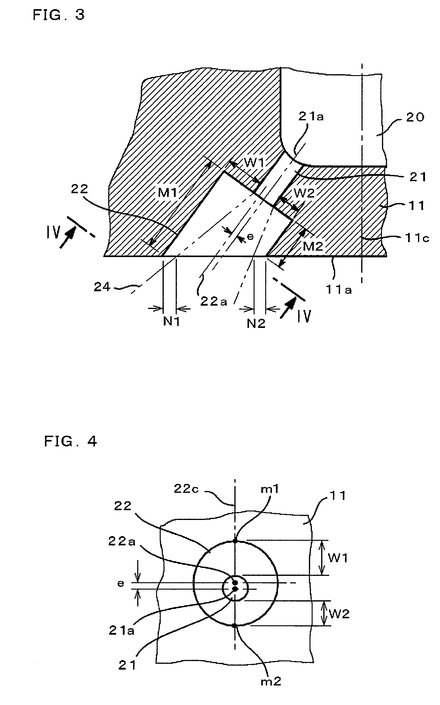
[0016]FIG. 1 is a sectional view illustrating one embodiment of the fuel injection valve of the present invention, FIG. 2 is an enlarged sectional view of the portion enclosed by a circle A of FIG. 1, FIG. 3 is an enlarged sectional view of the injection port of FIG. 2, and FIG. 4 is a sectional view taken along line IV-IV of FIG. 3 and showing the positional relationship of the injection port.

[0017]In these figures, the fuel injection valve 1 comprises a solenoid unit 2 for generating an electromagnetic force and a valve main body 3. The solenoid unit 2 is provided with a magnetic circuit including a core 4 which is a stationary core, a ring 5 made of nonmagnetic material, a holder 6 and a housing 7, the housing 7 having contained therein a coil 9 connected to a terminal 8. The valve main body 3 includes a valve seat member 11 having a valve set member end surface 11a and a valve seat 11b and at least one injection port 10, a body 13 to which a guide 12 is secured, an armature 14 w...

embodiment 2

[0030]FIG. 7 illustrates the second embodiment of the fuel injection valve of the present invention. In this example, the end face 11a of the valve seat member 11 is not planar but is conical surface or a protruding cone. In this case also, by providing a displacement or an eccentricity e to the central axis 22a of the second injection port 22 in the direction that W1>W2 is held (in the direction toward the shorter side line m2 of the shortest length M1 from the longer side line m1 of the longest length M2), the interference of the fuel spray pattern 24 can be avoided, so that the depth M of the second injection port 22 can be set deeper. In this case also, the valve seat end surface 11a of the valve seat member 11 is not planar, the lines that the vertical plane 22c passing through the central axis 11c of the valve seat end surface 11a and the central axis 22a of the second injection port 22 and the cylindrical inner wall surface of the second injection port 22 are the longer side ...

embodiment 3

[0031]FIG. 8 illustrates the third embodiment of the fuel injection valve of the present invention. In this example, a tapered wall 22e is connected between the second injection port 22 and the cylindrical inner wall 22d, decreasing a dead volume 23 defined between the second injection port 22 and the fuel spray pattern 24. Thus, the second injection port 22 may be either at least partially cylindrical or at least partially tapered to expand toward the exit.

[0032]With such structures, the volume of the second injection port 22 can be reduced, so that the fuel amount that resides within the second injection port 22 even after the fuel injection can be reduced. The residual fuel is the cause for generating the deposit, so that this embodiment can reduce the deposit amount deposited within the second injection port 22. The reason that the deposit in the second injection port 22 should be decreased is that the interference of the fuel spray pattern 24 easily occurs as the thickness of t...


PUM


Abstract

A fuel injection valve has a first and a second injection ports whose central axes are parallel to each other, the central axis of the second injection port is out of alignment with respect to the central axis of the first injection port so that, when the largest length M1 of a longer-side line along which a plane including the central axis of the valve seat member and the central axis of the second injection port intersects with an inner wall of the second injection port is larger than the shortest length M2 of a shorter-side line along which the above plane intersects with an inner wall of the second injection port, the distance W1 from the inner wall of the first injection port to the longer-side line of the second injection port as measured within the plane is larger than the distance W2 from the inner wall of the first injection port to the shorter-side line of the second injection port as measured within the plane.

Description

BACKGROUND OF THE INVENTION[0001]This invention relates to a fuel injection valve for use in an internal combustion engine for an automobile or the like and, particularly, to a fuel injection valve suitable for use with a direct combustion engine.[0002]The fuel injection valve disclosed in Japanese Patent Laid-Open No. 9-273458 has a structure in which a first injection port has provided at its downstream with a second injection port having a larger diameter than the first injection port, whereby the length of the first injection port can be adjusted by changing the depth of the second injection port. This allows the adjustment of the ratio L / D of the length L and the diameter D of the first injection port, so that the degree of freedom of the fuel spray pattern can improved. Also, since the opening end of the first injection port is not directly open at the end face of the valve seat member, the deposit such as carbon deposit in the first injection port can be suppressed.SUMMARY OF...

Claims


Application Information

Patent Timeline
IPC IPC(8): F02M51/00
CPCF02M51/061F02M61/1846F02M61/1813
Inventor KITAGAWA, KAZUNORIAOTA, MASAYUKIMUNEZANE, TSUYOSHI
Owner MITSUBISHI ELECTRIC CORP
Why Eureka
Try Eureka