
clutch structure

A clutch and friction ring technology, applied in the field of clutch structure, can solve problems such as size increase

Active Publication Date: 2021-05-28
HYUNDAI MOTOR CO LTD
View PDF14 Cites 0 Cited by
  • Summary
  • Abstract
  • Description
  • Claims
  • Application Information

AI Technical Summary

Problems solved by technology

Therefore, the size of the equipment (eg, actuator) that operates the clutch is also increased

Method used


Image

  • clutch structure
  • clutch structure
  • clutch structure

Examples


Embodiment Construction

[0031] The following descriptions are exemplary in nature only and are not intended to limit the invention, application, or use. It should be understood that throughout the drawings, corresponding reference numerals indicate similar or corresponding parts and features.

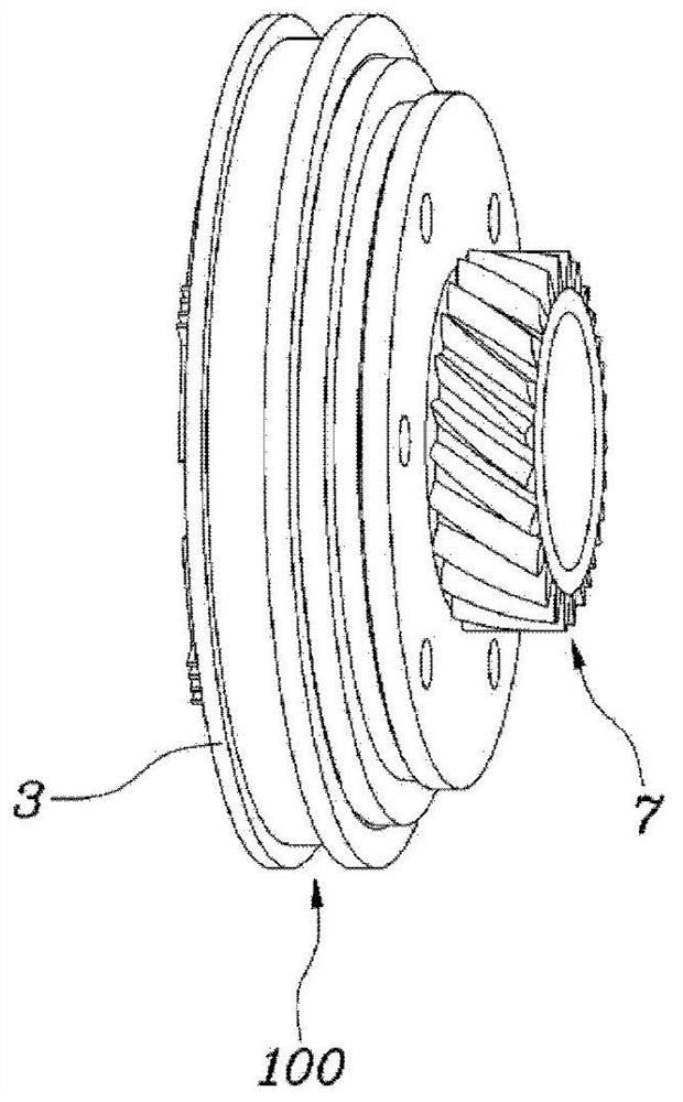
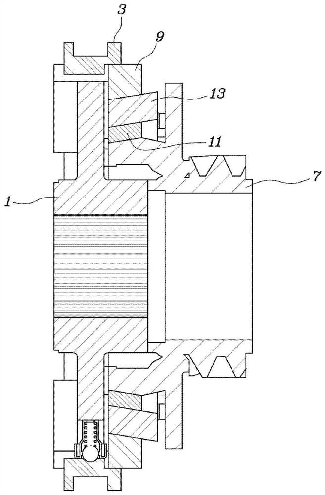
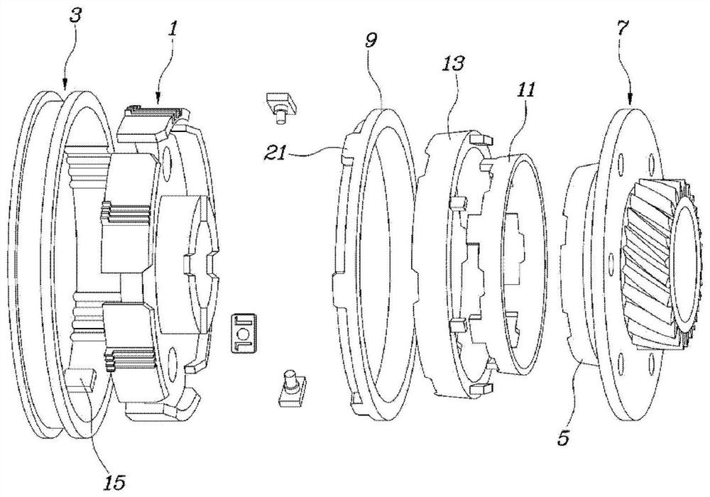
[0032] refer to Figure 1 to Figure 4 , the structure of the clutch 100 according to the present invention includes: a hub 1 fixed to the rotating shaft; a sleeve 3 mounted on the outer peripheral surface of the hub 1 to slide linearly; a clutch gear 7 mounted on the rotating shaft to rotate relative to the rotating shaft and The clutch cone 5 is integrally formed, and the clutch cone 5 protrudes toward the hub 1 in such a manner that the outer diameter gradually decreases; the first friction ring 9 is arranged between the clutch gear 7 and the hub 1 and is configured to be pressed toward the clutch gear 7 , so as to generate friction between the clutch cone 5 and the hub 1, thereby transmitting torque; the s...


PUM


Abstract

The present invention provides a clutch structure, including: a hub, which is fixed on the rotating shaft; a sleeve, which is installed on the outer peripheral surface of the hub, and is configured to slide linearly; a clutch gear, which is installed on the rotating shaft, and is configured to be relatively The rotating shaft rotates, the clutch gear is integrally formed with the clutch cone, and the clutch cone protrudes toward the hub in such a manner that the outer diameter gradually decreases; the first friction ring, which is arranged between the clutch gear and the hub, presses toward the clutch gear so that the clutch cone A frictional force is generated between the body and the hub to transmit torque; the second friction ring is configured to prohibit rotation relative to the hub and has an inner surface in contact with the outer surface of the clutch cone; and an intermediate cone configured to Inhibited from rotating relative to the clutch gear, the intermediate cone has an inner surface and an outer surface, wherein the second friction ring and the intermediate cone are provided with friction members on at least one of their inner and outer diameters.

Description

technical field [0001] The present invention relates to a clutch structure, more particularly to a clutch structure for a vehicle transmission. Background technique [0002] The statements in this section merely provide background information related to the present disclosure and may not constitute prior art. [0003] Generally, a plurality of clutches are used in a vehicle transmission to transmit or disconnect driving force between rotatable bodies that rotate relative to each other. [0004] Clutches are expected to have increased torque transfer capability and compact size. However, the size of the clutch generally increases proportionally with the increase in torque transfer capability. [0005] Furthermore, when the clutch is intended to transmit a relatively large torque, the force to operate the clutch must be increased. Therefore, the size of a device (for example, an actuator) that operates a clutch is also increased. [0006] Information disclosed in this cont...

Claims


Application Information

Patent Timeline
Patent Type & Authority Patents(China)
IPC IPC(8): F16D13/60F16D13/58
CPCF16D13/58F16D13/60F16D23/04F16D2023/065F16D2023/0681F16D13/64F16D2013/642
Inventor 朴钟闰宋坰
Owner HYUNDAI MOTOR CO LTD
Learn More