Fan speed control method, device and cooling method for projection system

A technology of fan speed and control method, which is applied in projection devices, cooling/ventilation/heating transformation, optics, etc., can solve the problems of electronic equipment not being able to cool down, affecting the performance of electronic equipment, etc., to ensure performance, prevent temperature rise, reduce noise effect

Active Publication Date: 2017-12-26
HISENSE
View PDF8 Cites 0 Cited by
  • Summary
  • Abstract
  • Description
  • Claims
  • Application Information

AI Technical Summary

Problems solved by technology

[0005] Embodiments of the present invention provide a fan speed control method, device, and heat dissipation method for a projection system, which are used to solve the problem that the fan speed control method in the prior art cannot cool down the electronic equipment in time and affect the performance of the electronic equipment

Method used


Image

  • Fan speed control method, device and cooling method for projection system
  • Fan speed control method, device and cooling method for projection system
  • Fan speed control method, device and cooling method for projection system

Examples


Embodiment 1

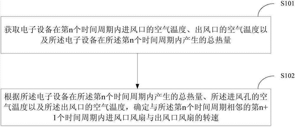
[0029] figure 1 It is a schematic flowchart of a fan speed control method according to an embodiment of the present invention.

[0030] see figure 1 , each step of the fan speed control method in the embodiment of the present invention is completed by the fan speed control device, and the method includes:

[0031] S101: Obtain the air temperature of the air inlet, the air temperature of the air outlet of the electronic device in the nth time period, and the total heat generated by the electronic device in the nth time period; n is an integer greater than or equal to 1 ;

[0032] Specifically, the air temperature of the air inlet and the air outlet of the electronic device can be measured in real time by thermistors installed at the air inlet and the air outlet respectively.

[0033] The total heat generated by the electronic device during the nth time period may be determined according to the input power and output power of the electronic device during the nth time period. ...

Embodiment 2

[0080] Figure 6 It is a schematic diagram of the frame structure of the fan control device according to the embodiment of the present invention.

[0081] see Figure 6 , the fan speed control device according to the embodiment of the present invention includes:

[0082] The obtaining module 610 is used to obtain the air temperature of the air inlet and the air outlet of the electronic device in the nth time period and the total heat generated by the electronic device in the nth time period; n is greater than or equal to an integer of 1;

[0083] The processing module 620 is configured to determine the time period corresponding to the nth time period according to the total heat generated by the electronic device within the nth time period, the air temperature of the air inlet hole, and the air temperature of the air outlet hole. The rotation speed of the air outlet fan in the n+1th time period adjacent to the cycle; wherein, the air inlet fan is installed in the air inlet, ...

Embodiment 3

[0098] Figure 7 It is a schematic flowchart of a heat dissipation method for a projection system according to an embodiment of the present invention.

[0099] see Figure 7 , an embodiment of the present invention also provides a heat dissipation method for a projection system, including:

[0100] S701: Obtain the air temperature of the air inlet, the air temperature of the air outlet of the projection system in the nth time period, and the total heat generated by the projection system in the nth time period; n is greater than or equal to 1 Integer; n is an integer greater than or equal to 1;

[0101] S702: According to the total heat generated by the projection system in the nth time period, the air temperature of the air inlet hole, and the air temperature of the air outlet, determine the time period adjacent to the nth time period The speed of the air inlet fan and the air outlet fan in the n+1th time period; wherein, the air inlet fan is installed in the air inlet, and...


PUM


Abstract

The invention provides a fan speed control method, a fan speed control device and a projection system cooling method. The method comprises the following steps: acquiring the air temperature of the air inlet and the air temperature of the air outlet of electronic equipment in an nth time period and the total amount of heat generated by the electronic equipment in the nth time period, wherein n is an integer greater than or equal to 1; and determining the speed of a fan at the air inlet and the speed of a fan at the air outlet in an (n+1)th time period adjacent to the nth time period according to the total amount of heat generated by the electronic equipment in the nth time period, the air temperature of the air inlet and the air temperature of the air outlet. According to the fan speed control method, the fan speed control device and the projection system cooling method provided by the embodiments of the invention, through control on accumulation of heat in the electronic equipment, the speed of the fans can be adjusted before temperature rise, and the electronic equipment can be cooled in a timely manner.

Description

technical field [0001] The invention relates to the field of electronic products, in particular to a method and device for controlling the rotational speed of a fan and a heat dissipation method for a projection system. Background technique [0002] When electronic devices (such as computers, laser projectors, etc.) work, they usually generate a lot of heat in the system. The internal temperature of the system is too high, which will damage the performance of electronic equipment. Therefore, a fan needs to be installed in the electronic device for heat dissipation. If the fan speed is too slow, it will cause poor heat dissipation performance and affect the performance of electronic equipment. If the fan speed is too fast, it will increase the noise generated during the operation of the electronic equipment and waste system resources. Therefore, it is necessary to quickly and accurately control the rotational speed of the fan in the electronic device. [0003] The common f...

Claims


Application Information

Patent Timeline
Patent Type & Authority Patents(China)
IPC IPC(8): H05K7/20G03B21/16
CPCG03B21/16H05K7/20209
Inventor 郭大勃王晨星王振
Owner HISENSE
Why Eureka
Try Eureka