Washing machine door lock detection structure and method

A detection structure and detection method technology, applied in the field of washing machines, can solve problems such as poor safety of washing machines, door lock detection errors, etc., and achieve the effects of improving safe usability, safe and reliable work, and simple structure

Active Publication Date: 2018-06-05
QINGDAO JIAONAN HAIER WASHING MACHINE +1
View PDF5 Cites 21 Cited by
  • Summary
  • Abstract
  • Description
  • Claims
  • Application Information

AI Technical Summary

Problems solved by technology

[0005] Another object of the present invention is to provide a method for door lock detection using the above-mentioned washing machine door lock detection structure, which can effectively solve the problem of poor safety of the washing machine due to door lock detection errors in the existing washing machine door switch detection device

Method used


Image

  • Washing machine door lock detection structure and method
  • Washing machine door lock detection structure and method
  • Washing machine door lock detection structure and method

Examples


Embodiment 1

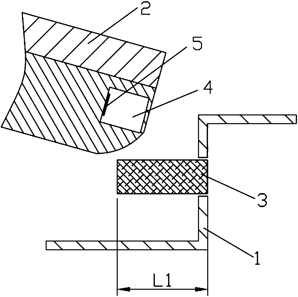
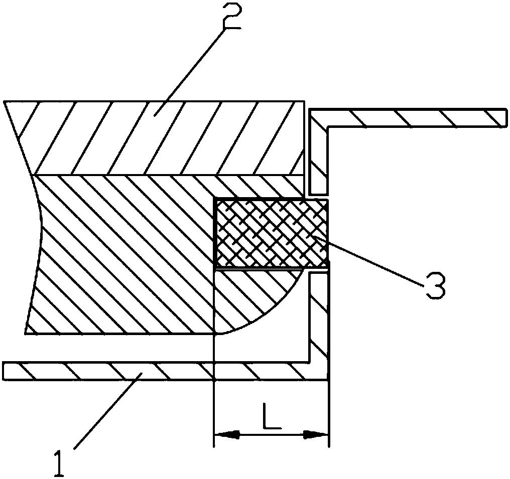
[0034] Such as Figure 1-Figure 2 As shown, this embodiment provides a preferred washing machine door lock detection structure, which includes a control panel base 1, one side of the control panel base 1 is rotatably connected to the upper cover 2, and a door lock lock is installed on the control panel base 1. The tongue 3 and the upper cover 2 are provided with a lock hole 4 matched with the lock tongue 3. When the upper cover 2 is closed, the controller can control the lock tongue 3 to extend into the lock hole 4, thereby locking the upper cover 2. This structure also includes a detection switch for detecting the extension state of the lock tongue 3. When the upper cover 2 is not closed in place, there is no obstacle in the extension direction of the lock tongue 3, so it can be fully extended. At this time, the detection switch will go up. The cover 2 unlocked signal is sent to the controller, and the controller controls the washing machine to give an alarm to remind the use...

Embodiment 2

[0040] This embodiment proposes another door lock detection structure of the washing machine, which is basically the same as the door lock detection structure described in Embodiment 1, the difference being that the detection switch is different.

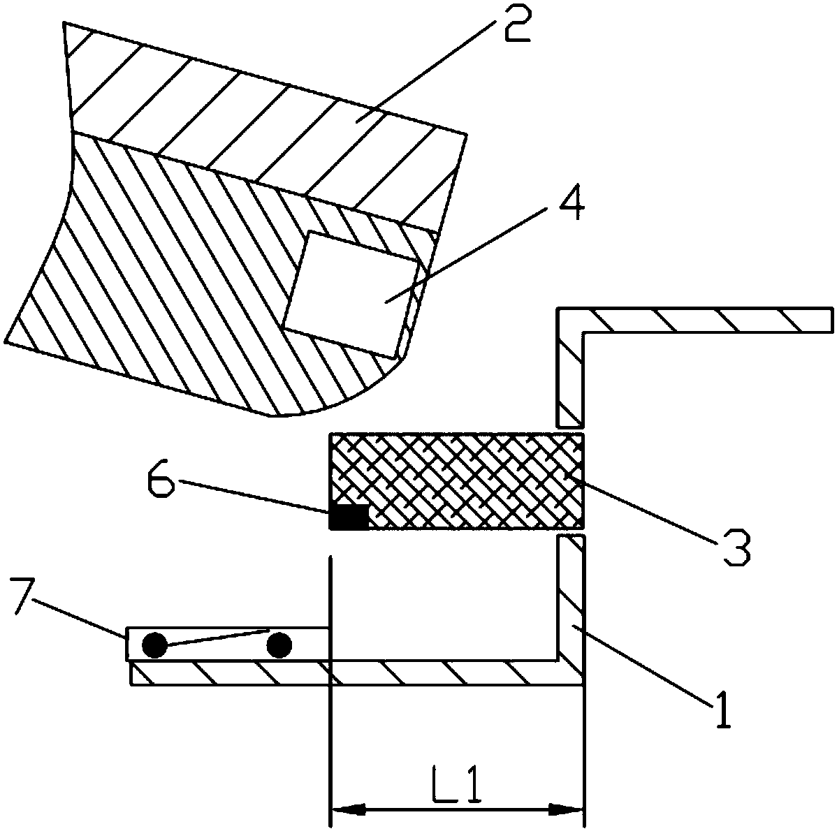
[0041] Such as Figure 3-Figure 4 As shown, the detection switch of this embodiment includes a magnet 6 arranged at the extended end of the deadbolt 3 and an induction switch 7 arranged on the control panel base 1. Here, the induction switch 7 is located in the extension direction of the deadbolt 3 and senses The horizontal distance between the switch 7 and the fixed end of the deadbolt 3 (that is, the exit of the mounting hole) is L1. When the lock tongue 3 is not blocked and the extension length reaches L1, the magnet 6 closes the induction switch 7, and the induction switch 7 feeds back a signal that the upper cover 2 is not locked to the controller, and the washing machine does not run; and when the lock tongue 3 is in contact w...

Embodiment 3

[0044] This embodiment proposes yet another washing machine door lock detection structure, which combines the structural features of Embodiment 1 and Embodiment 2. The detection switch includes both an electromagnetic switch 5 and an inductive switch 7 .

[0045] Specifically, such as Figure 5-Figure 6 As shown, an electromagnetic switch 5 is provided on the inner end surface of the lock hole 4, a magnet 6 is provided on the protruding end of the deadbolt 3, and an induction switch 7 is provided on the control panel base 1 at the same time. When the upper cover 2 is closed in place, the lock tongue 3 extends into the lock hole 4, and when the length reaches L (0


PUM


Abstract

The invention discloses a washing machine door lock detection structure and relates to the technical field of washing machines. The structure comprises a control panel base, an upper cover, a door lock and a controller, a spring bolt of the door lock is arranged on the control panel base, and a lock hole of the door lock is formed in the upper cover; the spring bolt stretches out or retracts backunder control of the controller, the structure further comprises a detection switch, and when the upper cover is not closed in place, the spring bolt is not blocked and completely stretches out, and the detection switch sends an upper cover non-locking signal to the controller at this moment; when the upper cover is closed in place, the spring bolt is blocked by the lock hole and partially stretches into the lock hole, and the detection switch sends an upper cover locking signal to the control at this moment. The invention further discloses a washing machine door lock detection method. According to the washing machine door lock detection structure, the stretching state of the spring bolt is detected through the detection switch, whether or not the upper cover is truly closed is accuratelyjudged according to the difference of the stretching length of the spring bolt, the washing machine safety problem caused by inaccurate detection signals in the process of locking the upper cover of an existing door lock is avoided, and the safe usability of the washing machine is improved.

Description

technical field [0001] The invention relates to the technical field of washing machines, in particular to a washing machine door lock detection structure and detection method capable of preventing the washing machine from running when the door lock is not locked. Background technique [0002] At present, during the operation of the washing machine, in order to prevent the user from accidentally inserting his hand into the tub and causing accidental injury, a door lock is usually installed in the upper cover, and the upper cover and the control panel seat are locked by the door lock to ensure that the user safety. Specifically, first, the door switch detection device of the washing machine detects the opening and closing state of the upper cover. If it is detected that the upper cover is closed, the dead bolt or lock hook of the door lock will be stretched out to engage with the corresponding lock of the upper cover. hole, so that the upper cover cannot be opened, and then t...

Claims


Application Information

Patent Timeline
Patent Type & Authority Applications(China)
IPC IPC(8): D06F39/14D06F37/42
CPCD06F2224/00D06F37/42D06F39/14
Inventor 王得军徐雯婷张皓钧今井俊次郑玉强邢福涛
Owner QINGDAO JIAONAN HAIER WASHING MACHINE
Why Eureka
Try Eureka