Faucet structure

A faucet and lead plug technology, applied in the field of faucets, can solve the problems of inconvenient assembly and disassembly, inconvenient use and installation, etc., and achieve the effects of convenient assembly and disassembly, simple structure, and improved function expansion and application.

Pending Publication Date: 2018-06-05
FOSHAN VIOMI ELECTRICAL TECH +2
View PDF7 Cites 2 Cited by
  • Summary
  • Abstract
  • Description
  • Claims
  • Application Information

AI Technical Summary

Problems solved by technology

[0002] Existing faucets include an integrated faucet body and base, and an induction element that can control the water passage of the faucet body is provided on the faucet body and / or the base, and the induction element is electrically connected to the lead plug; however, the faucet with the above-mentioned traditional structure , there are still the following deficiencies: (1) The integrated connection structure between the faucet body and the base causes a lot of inconvenience to users in use and installation; see figure 1 As shown, since the faucet body 21 and the base 22 cannot be disassembled together, when installing, first insert all the parts including the faucet 21 and the base 22 into the installation hole 23, and then use the fastening threaded sleeve 24 to fix the faucet on the table. 25; however, when the fastening thread is rotating, the main body of the faucet will also rotate accordingly, so the user needs to hold the main body 21 of the faucet with one hand, and then rotate the fastening thread sleeve 24 with the other hand, and at this time , the installer generally squats below the table top 25. If the table top 25 is relatively wide, one person cannot complete the installation. It may be necessary to add another person to help fix the faucet body 21 to achieve a good installation, causing many problems for the user to install and disassemble. inconvenient

Method used


Image

  • Faucet structure
  • Faucet structure
  • Faucet structure

Examples


Embodiment Construction

[0026] The present invention will be further described below in conjunction with accompanying drawing and embodiment:

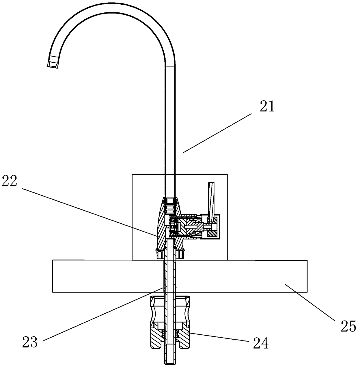
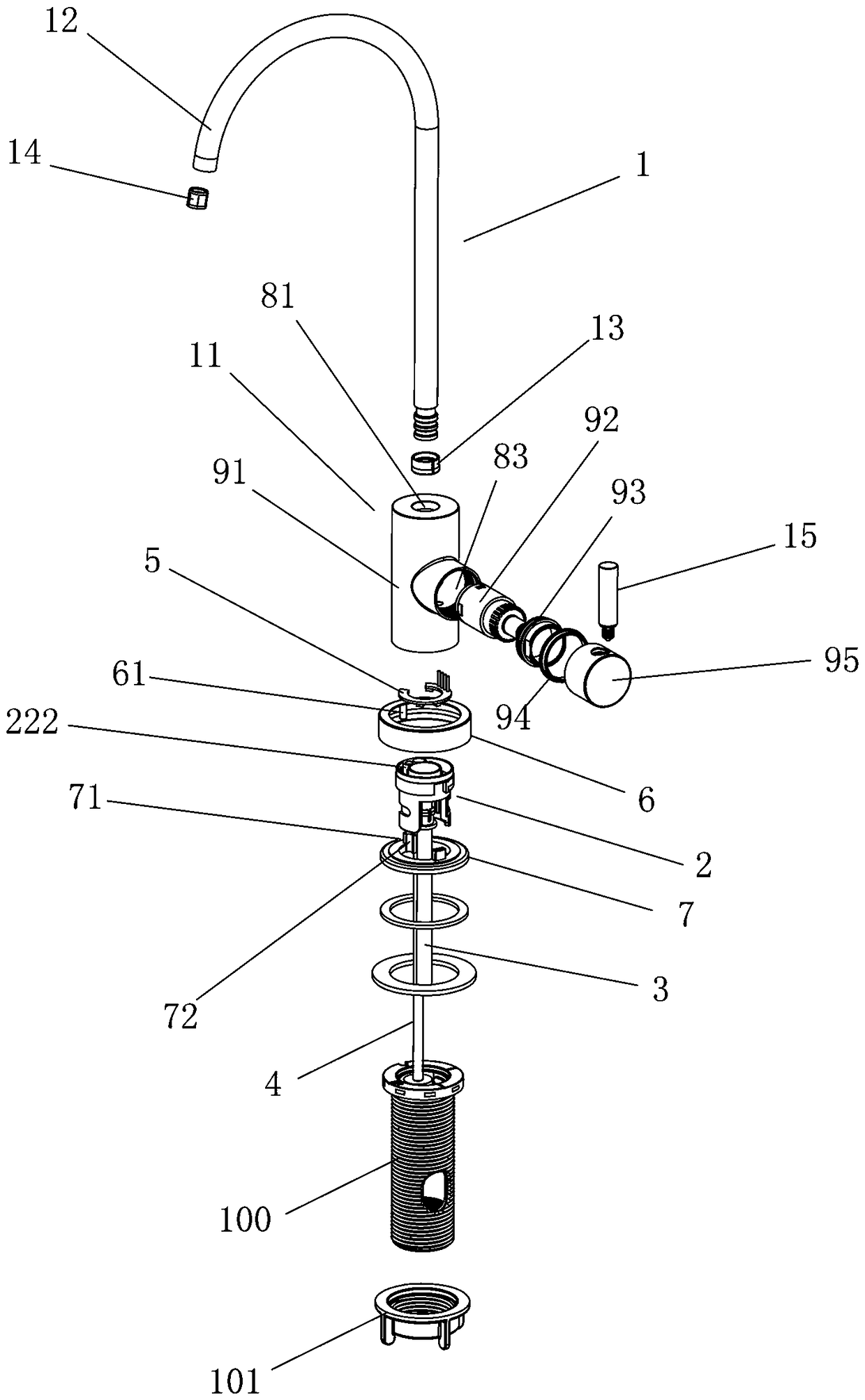
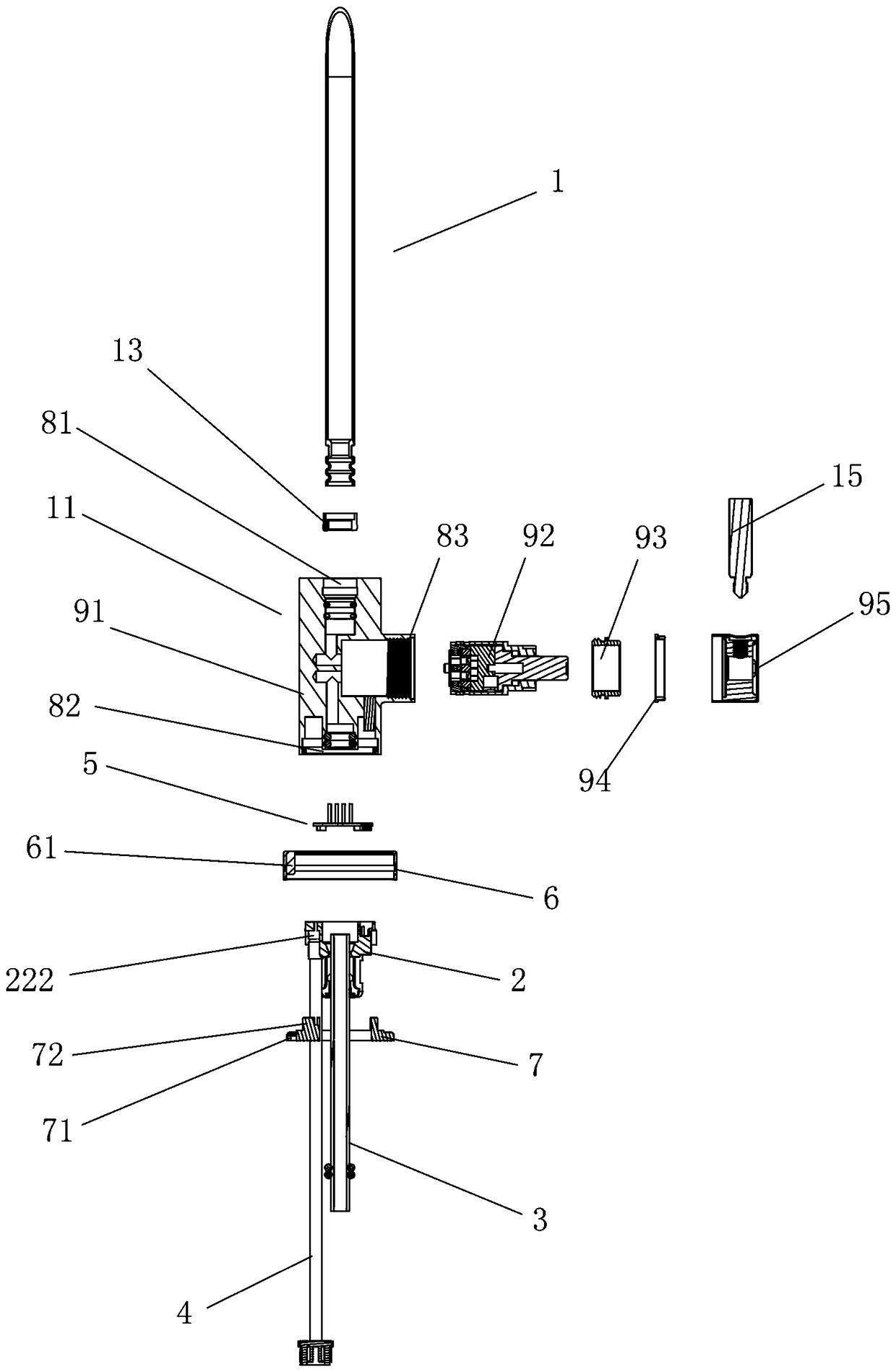
[0027] see figure 2 and image 3 As shown, a faucet structure includes a faucet body 1 and a base 2. The base 2 is provided with a lead plug 4 and a water diversion pipe 3. The base 2 is installed on the lower part of the faucet body 1 in a detachable manner. Its characteristics Yes, it also includes a circuit board 5, a pressure plate 6 and a light strip 7. The circuit board 5 is set on the base 2 and placed between the base 2 and the faucet body 1. The pressure plate 6 and the light strip 7 are respectively sleeved on the base. The outer wall of the base 2 , the circuit board 5 and the light strip 7 are electrically connected to the lead plug 4 respectively, wherein the circuit board 5 is a ring lamp circuit board installed on the top of the base 2 .

[0028] In this embodiment, the faucet body 1 includes a faucet body 11, a spout 12, a spout sealing rin...


PUM


Abstract

The invention discloses a faucet structure which comprises a faucet body and a base. A lead plug and a drainage pipe are arranged on the base. The base is detachably installed at the lower portion ofthe faucet body. The faucet structure further comprises a circuit board, a pressing plate and a lamp band. The circuit board is arranged on the base and arranged between the base and the faucet body,the outer wall of the base is sleeved with the pressing plate and the lamp band separately, and the circuit board and the lamp band are electrically connected with the lead plug separately; accordingto the faucet structure, due to the fact that the faucet body and the base are detachably connected, during installation, the faucet body and the base are installed at the upper and lower portions ofthe tabletop respectively and connected and fixed to the tabletop through a connecting piece, the whole process is simple and easy, and operation can be completed by one person, and a user can assemble and disassemble the structure conveniently; then, by additionally arranging the lamp band, an electrical apparatus element is arranged on the faucet, the function extension and application of the product are improved to a certain degree, product application and popularization are facilitated, and the faucet structure is simple and reasonable in structure.

Description

technical field [0001] The invention relates to the technical field of faucets, in particular to a detachable faucet structure. Background technique [0002] Existing faucets include an integrated faucet body and a base, and an induction element that can control the water passage of the faucet body is arranged on the faucet body and / or the base, and the induction element is electrically connected to the lead plug; however, the faucet with the above-mentioned traditional structure , there are still the following deficiencies: (1) The integral connection structure between the faucet body and the base causes a lot of inconvenience to users in use and installation; see figure 1 As shown, since the faucet body 21 and the base 22 cannot be disassembled together, when installing, first insert all the parts including the faucet 21 and the base 22 into the installation hole 23, and then use the fastening threaded sleeve 24 to fix the faucet on the table. 25; however, when the fasten...

Claims


Application Information

Patent Timeline
IPC IPC(8): F16K31/04F16K51/00B01D35/04
CPCB01D35/04F16K31/046F16K51/00
Inventor 陈小平
Owner FOSHAN VIOMI ELECTRICAL TECH
Why Eureka
Try Eureka