
Novel photoflood lamp

A photographic lamp, a new type of technology, applied in photography, optics, instruments, etc., can solve the problem of inconvenient adjustment of the angle of the lamp body, and achieve the effect of solving the inconvenient and convenient adjustment of the angle

Inactive Publication Date: 2018-06-05
ZHENGZHOU LONGWEI ELECTRONICS TECH CO LTD
View PDF0 Cites 0 Cited by
  • Summary
  • Abstract
  • Description
  • Claims
  • Application Information

AI Technical Summary

Problems solved by technology

[0003] In order to solve the above problems, the present invention provides a new type of photographic lamp to solve the problem of inconvenient adjustment of the angle of the lamp body of the existing photographic lamp

Method used


Image

  • Novel photoflood lamp

Examples


Embodiment Construction

[0014] The present invention will be described in detail below in conjunction with the accompanying drawings and specific embodiments.

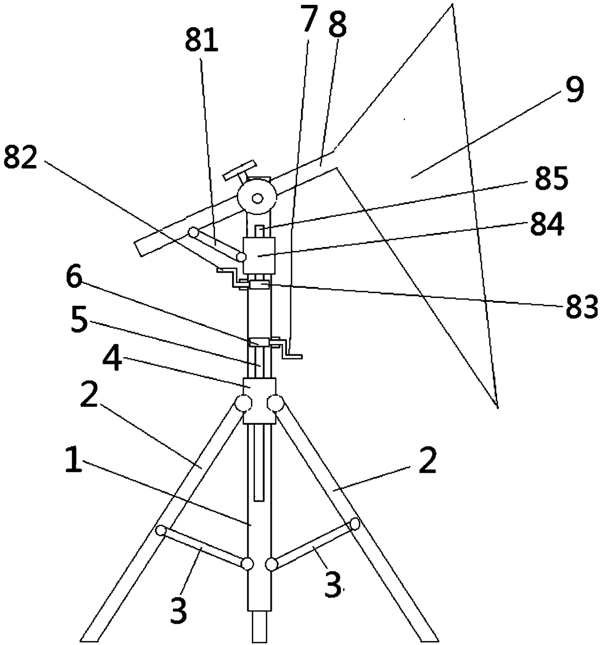
[0015] Embodiments of the novel photographic light of the present invention are as follows: figure 1 As shown, a photographic lamp stand includes a frame body on which a lamp body 9 is installed through a cross bar 8, the frame body includes a vertical rod 1, and the upper end of the vertical rod is hingedly connected with a cross bar 8, and the cross bar 8 A light 9 body is installed at one end of the cross bar 8, and the other end of the cross bar 8 is hingedly connected with a connecting rod 81. The guide movement on the vertical rod is equipped with a first slider 84 that is hingedly connected with the end of the connecting rod away from the cross bar. The rod is also rotatably equipped with a first lead screw 85 that is screw-fitted with the first slide block, and the vertical rod is also provided with an adjustment handle 82 whose rotat...


PUM


Abstract

The invention relates to a novel photoflood lamp. When the novel photoflood lamp is in use, an adjustment handle is rotated to drive a first screw rod to rotate through a turbo-worm mechanism; the first screw rod is spirally matched with a first slider, so that the first slider is driven to move up and down when the first screw rod rotates; and when the first slider moves up and down, a connectingrod drives a cross bar to rotate around a hinge point of the cross bar and a vertical bar, so that the cross bar drives a lamp body to swing, and the angle of the lamp body is adjusted. As the angleof the lamp body can be conveniently adjusted by the adjustment handle, the problem that the angle of a lamp body of a conventional photoflood lamp is inconvenient to adjust is solved.

Description

technical field [0001] The invention relates to a novel photographic lamp. Background technique [0002] The photography light plays a very important role in photography. It can help the photographer to shoot better and make the final shooting effect better. The photography light includes a frame and a lamp body. The lamp body is installed on the frame through a cross bar. , The cross bar and the frame body are fastened by bolts. When the angle of the lamp body needs to be adjusted, the bolts need to be loosened to make the cross bar rotate relative to the frame body. This makes it inconvenient to adjust the angle of the lamp body of the photography light in the morning. Contents of the invention [0003] In order to solve the above problems, the present invention provides a new type of photographic light to solve the problem of inconvenient adjustment of the angle of the lamp body of the existing photographic light. [0004] In order to achieve the above object, the nove...

Claims


Application Information

Patent Timeline
Patent Type & Authority Applications(China)
IPC IPC(8): G03B15/02
CPCG03B15/02
Inventor 王波
Owner ZHENGZHOU LONGWEI ELECTRONICS TECH CO LTD
Learn More